Flywheel lock

a technology of locking device and flywheel, which is applied in the direction of spring/damper, mechanical equipment, springs, etc., can solve the problem that fixing bolts or nuts may require large torque to rota

Active Publication Date: 2022-11-22
FEDERICO NORA FRANCISCO JAVIER
View PDF7 Cites 0 Cited by
  • Summary
  • Abstract
  • Description
  • Claims
  • Application Information

AI Technical Summary

Benefits of technology

[0009]Because the present device does not interface with a long section of the teeth, there is no need to match the specific tooth patterning. Instead, one end of the device is pressed into the gap between two teeth so as to hold the flywheel in place. The opposite end of the device also contacts the teeth of the flywheel but does not need to fit at any particular part of the tooth pattern. For example, the second end does not need to fit exactly in a gap between two teeth but may instead contact a side of one of the teeth. This second contact point may serve to hold the device in the proper orientation so that the first end of the device solidly engages with the teeth and may also provide support for the device to be wedged in place. This design eliminates the need for a specific distance between the two ends of the device based on the tooth pattern and allows a single device to interface with a variety of flywheel configurations.
[0010]The device of the present invention does not feature an arm with a hole for a bolt to go through but rather an arched locking member. The arched locking member allows the device to be wedged between the flywheel and a fixed feature or bolt without having been actually bolted in place. Because of the shape of the arched locking member, the device can work with a variety of configurations in which the fixed feature or bolt has varying distance from the flywheel. This allows for universal use of the device with a variety of different engine configurations. Additionally, because the device does not need to be bolted in place, the nearby bolt does not need to be removed and passed through the device. This difference from the prior art allows for the device of the present invention to be installed and remove much more quickly and conveniently than previously developed flywheel locking devices.

Problems solved by technology

Because of the importance of the flywheel, the fixing bolts or nuts may require large amounts of torque to rotate.

Method used


Image

  • Flywheel lock
  • Flywheel lock
  • Flywheel lock

Examples


Embodiment Construction

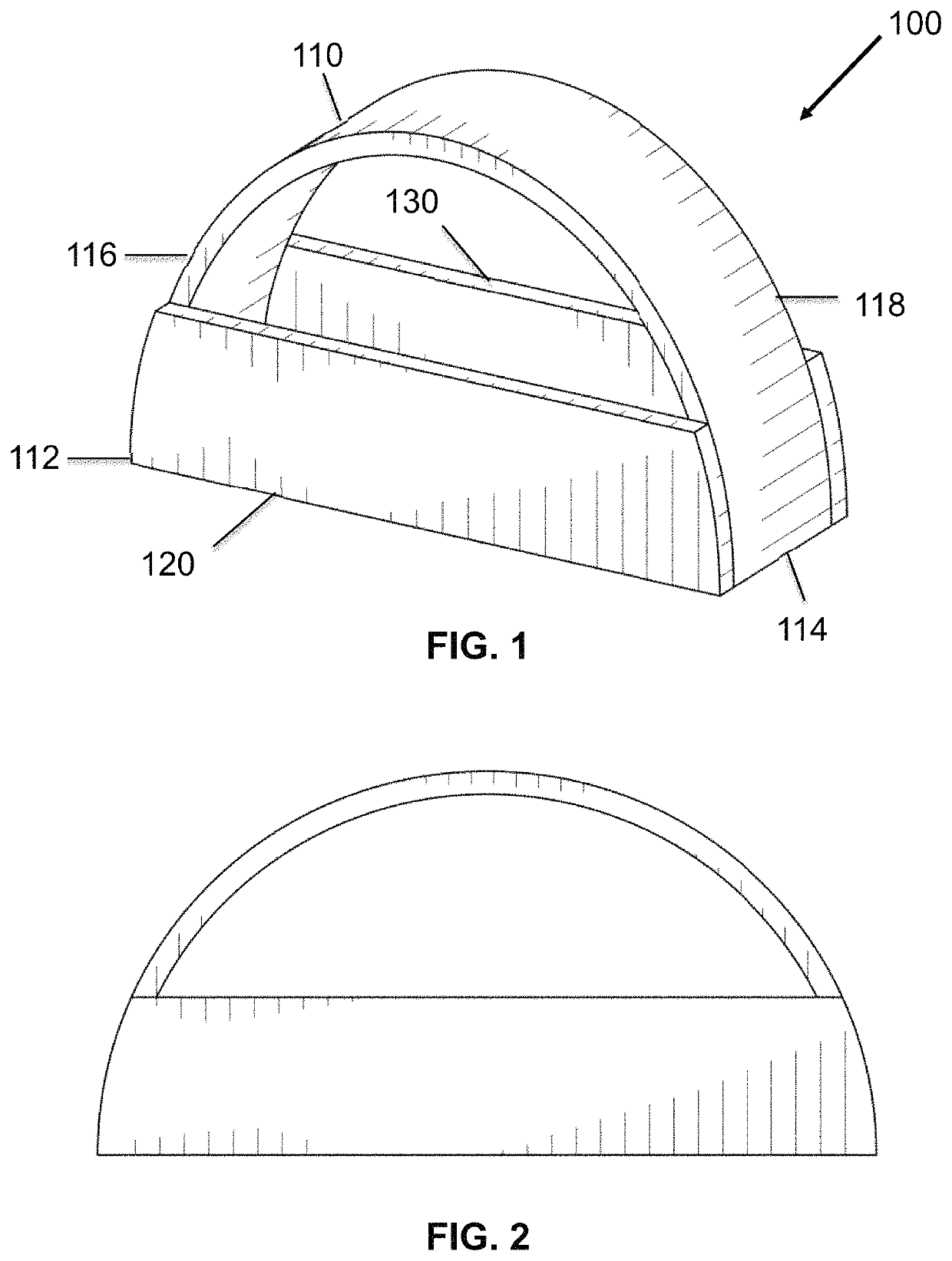
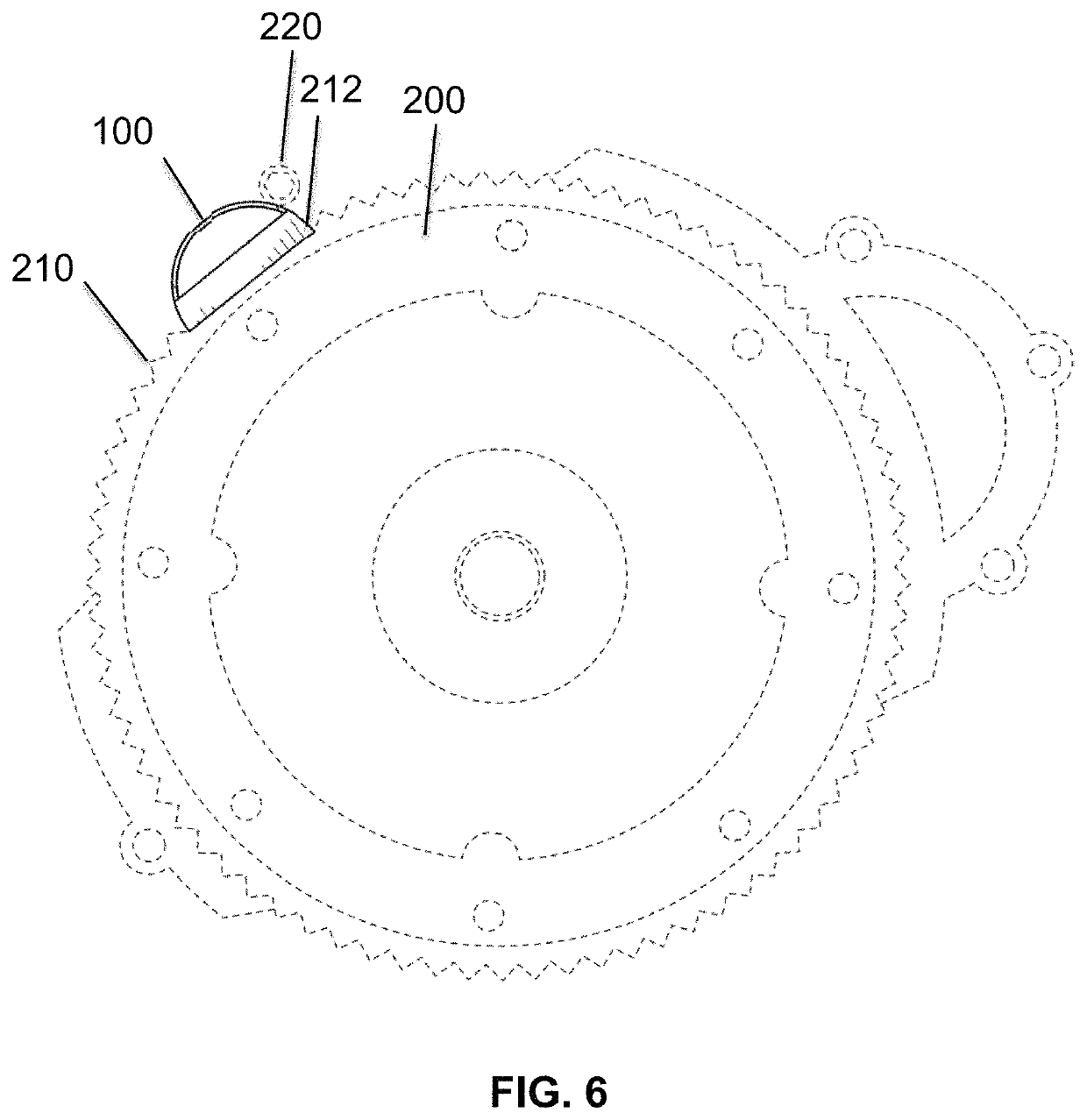
[0020]Following is a list of elements corresponding to a particular element referred to herein:[0021]100 flywheel locking device[0022]110 locking member[0023]112 first end[0024]114 second end[0025]116 first side[0026]118 second side[0027]120 first guide member[0028]130 second guide member[0029]200 flywheel[0030]210 teeth[0031]212 gap[0032]220 bolt

[0033]Referring now to FIG. 1, the present invention features a flywheel locking device (100). In one embodiment, the flywheel locking device (100) may comprising an arched locking member (110), a first guide member (120), and a second guide member (130). In some embodiments, the arched locking member (110) may have a first end (112) and a second end (114). In further embodiments, the first guide member (120) may be attached to a first side (116) of the locking member (110) between the first end (112) and the second end (114). In yet further embodiments, the second guide member (130) may be attached to a second side (118) of the locking mem...


PUM


Abstract

A universal flywheel locking device which is configured to fit flywheels with a variety of sizes and tooth patterns. The device may feature an arched locking member and two guide members attached to the sides of the locking member. The locking member is configured to wedge the device between a fixed feature or bolt and a flywheel so as to prevent rotation of the flywheel. The first end of the locking member may be configured to fit within a gap between two of a plurality of teeth of the flywheel so as to lock the flywheel.

Description

CROSS-REFERENCES TO RELATED APPLICATIONS[0001]This application is a non-provisional and claims benefit of U.S. Provisional Application No. 62 / 815,750 filed Mar. 8, 2019, the specification of which is incorporated herein in its entirety by reference.FIELD OF THE INVENTION[0002]The present invention relates to locking devices for hindering the rotation of a gear. More specifically, the present invention relates to locking devices for locking a flywheel of an internal combustion engine.BACKGROUND OF THE INVENTION[0003]The flywheel is an integral part of the internal combustion engine. It is connected to the crankshaft of the engine and helps to balance the rotating crankshaft. Power can be transferred through the flywheel from the engine to the transmission. The circumference of the flywheel generally features teeth which engage with the starter motor.[0004]In the course of engine maintenance or repair, it is sometimes necessary to tighten or loosen the bolts or nuts which hold the fly...

Claims


Application Information

Patent Timeline
Patent Type & Authority Patents(United States)
IPC IPC(8): F16H33/02F16F15/30
CPCF16H33/02F16F15/30F16F2230/0041
Inventor FEDERICO NORA, FRANCISCO JAVIER
Owner FEDERICO NORA FRANCISCO JAVIER
Why Eureka
Try Eureka