Fire suppression systems and methods

a technology of fire suppression and suppressant, applied in fire rescue, medical science, dental surgery, etc., can solve the problems of difficult to apply such suppressants in sufficient volume or with sufficient speed to control fire before significant damage, and achieve the effect of suppressing fir

Inactive Publication Date: 2010-03-11
INTEGRATED SYST EXCELLENCE CORP
View PDF6 Cites 33 Cited by
  • Summary
  • Abstract
  • Description
  • Claims
  • Application Information

AI Technical Summary

Benefits of technology

The invention provides tools and techniques to stop fires. It does this by sending a signal that generates waves that disrupt the relationship between electrons and ions in the fire. This results in a repulsion between the ions, which disperses the plasma and stops the fire from spreading.

Problems solved by technology

The patent text discusses the traditional methods of fire suppression, which involve using chemicals or smothering agents to disrupt the fire's chemical reactions or deprive it of oxygen. However, these methods are often impractical or ineffective in applications such as wild fires or in vehicles. Additionally, the use of some suppressants is hazardous to the environment. Therefore, the technical problem addressed in the patent is the need for tools and techniques to suppress fires without the use of smothering agents.

Method used


Image

  • Fire suppression systems and methods
  • Fire suppression systems and methods
  • Fire suppression systems and methods

Examples


Embodiment Construction

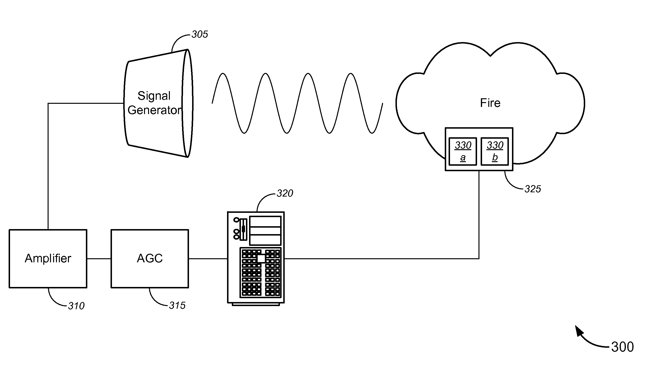
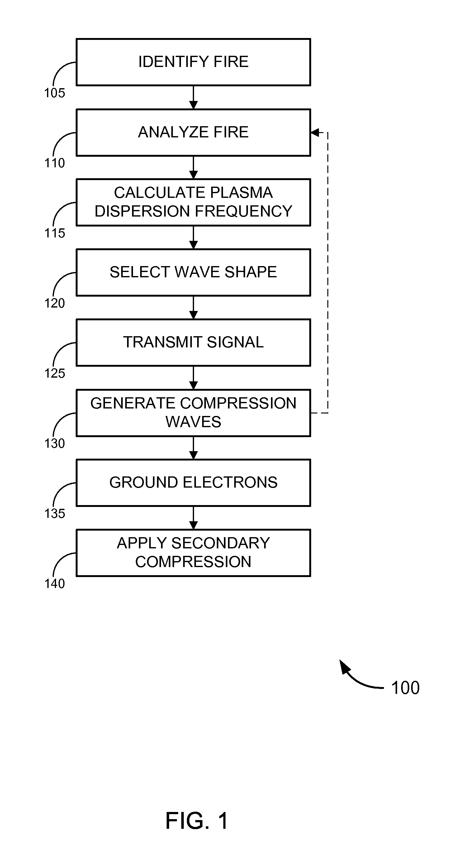
[0022]While various aspects and features of certain embodiments have been summarized above, the following detailed description illustrates a few exemplary embodiments in further detail to enable one of skill in the art to practice such embodiments. In the following description, for the purposes of explanation, numerous specific details are set forth in order to provide a thorough understanding of the described embodiments. It will be apparent, however, to one skilled in the art that other embodiments of the present invention may be practiced without some of these specific details. In other instances, well-known structures and devices are shown in block diagram form. Several embodiments are described herein, and while various features are ascribed to different embodiments, it should be appreciated that the features described with respect to one embodiment may be incorporated with other embodiments as well. By the same token, however, no single feature or features of any described emb...


PUM


Abstract

Tools and techniques for suppressing fires. Such tools might transmit a signal that generates one or more waves (which might be mechanical waves, electromagnetic waves, and/or the like) that is sufficient to disrupt the relationship between the electrons in a fire and the ionized nuclei to which those electrons are attracted. The resulting repulsion (between the nuclei and/or the electrons) that form the plasma of the fire can serve to disperse the plasma, thereby suppressing the fire.

Description


Claims


Application Information

Patent Timeline
Owner INTEGRATED SYST EXCELLENCE CORP
Why Eureka
Try Eureka