
Camera module thin film heater and camera module having same

A film heater, camera module technology, applied in the camera body, camera, ohmic resistance heating, etc., can solve the problems of camera module burnout, long consumption, design difficulties, etc., to suppress fire and avoid frost. , the effect of reducing manufacturing costs

Active Publication Date: 2018-05-11
LG INNOTEK CO LTD
View PDF7 Cites 8 Cited by
  • Summary
  • Abstract
  • Description
  • Claims
  • Application Information

AI Technical Summary

Problems solved by technology

[0005] Although a heat wire that generates heat is provided on the camera module to avoid frost, ice, and condensation on the lens, a temperature sensor and a temperature control unit must be additionally installed on the camera module to prevent frost, condensation, and condensation on the lens. ice and condensation
[0006] In addition, it takes a long time to use the heating wire to increase the lens temperature to the specified temperature to prevent frost, ice and condensation on the lens
[0007] Especially when the outdoor temperature is very low, it takes a long time to heat the lens temperature to the target temperature, on the contrary, if the outdoor temperature is high or the temperature of the camera module is high, there is a risk of the camera module being burned out when the heating wire generates heat also very high
[0008] Meanwhile, when using a thermal wire that uses a temperature sensor and a temperature control unit to control the temperature to prevent lens frosting, icing, and dew condensation, it is very difficult in design to mount the temperature sensor directly on the lens
In addition, when the temperature sensor is arranged at a position separated from the lens because it is difficult to mount the temperature sensor directly on the lens, it is difficult to accurately control the temperature on the lens because it is difficult to accurately sense the temperature

Method used


Image

  • Camera module thin film heater and camera module having same
  • Camera module thin film heater and camera module having same
  • Camera module thin film heater and camera module having same

Examples


Embodiment Construction

[0048] It should be understood that only elements necessary for understanding the exemplary embodiments will be described, and for brevity and clarity, detailed descriptions of well-known functions, configurations or constructions are omitted so as not to obscure the description of the invention with unnecessary detail. .

[0049] Unless otherwise defined, all terms used herein have the same meaning as commonly understood by one of ordinary skill in the art to which this invention belongs. It will be further understood that terms such as those defined in commonly used dictionaries should be interpreted to have a meaning consistent with their meanings in the relevant art and in the context of the present invention.

[0050]It should be understood that the exemplary embodiments described in this specification and the configurations shown in the drawings are only preferred exemplary embodiments and do not represent all technical ideas of the present invention, and therefore many ...


PUM


Abstract

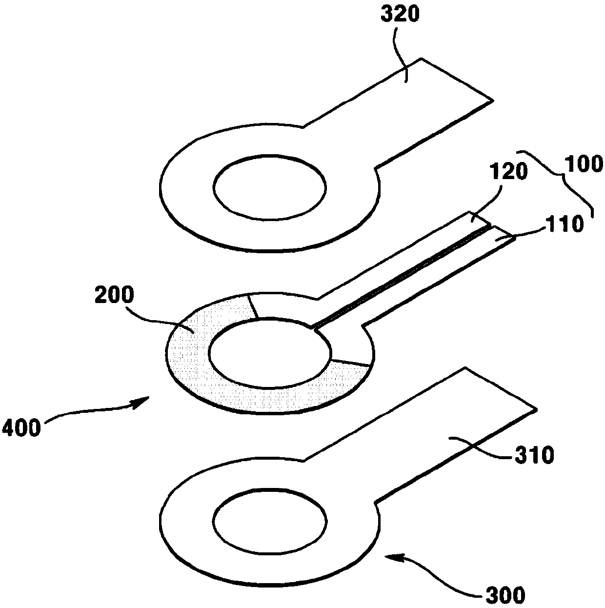
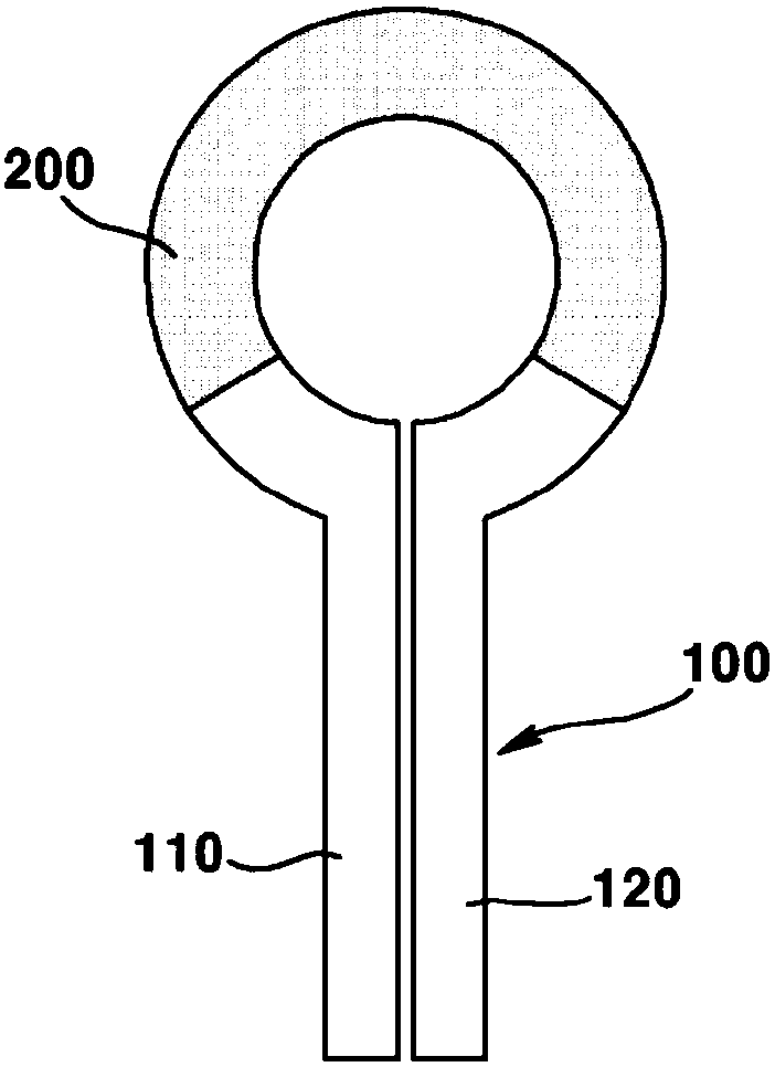
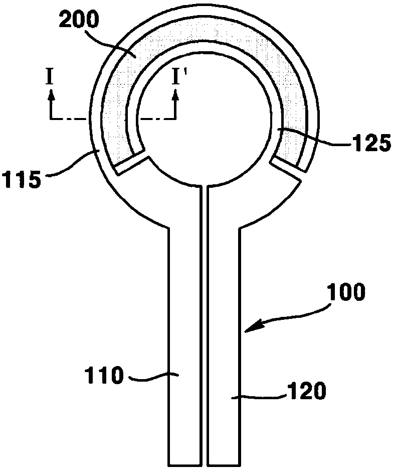
The present invention provides a camera module thin film heater and a camera module having the same, the camera module thin film preventing and avoiding glare, condensation and freezing by reaching atarget temperature of a lens within a short period of time, suppressing the generation of fire due to overheating even when operated in a high temperature environment, and not including a temperaturesensor and a temperature control unit, thereby greatly reducing the manufacturing cost. The camera module thin film heater comprises: an electrode; a thin film heating body electrically connected to the electrode and having a variable resistance corresponding to a heating temperature; and an insulating member surrounding the electrode and the thin film heating body.

Description

technical field [0001] Teachings according to exemplary and non-limiting embodiments of the present invention relate generally to camera module film heaters and camera modules having the same. Background technique [0002] Typically, portable communication devices, such as smartphones and tablets, are equipped with camera modules by players to take photos or images. [0003] The camera module may include an image sensor converting incident external light into an image, and at least one lens disposed on an optical axis of the image sensor. [0004] The lens is affected by external air due to being arranged outside the camera module, so that the lens is frequently frosted, iced, and dewed. When the lens is frosted, icy and dewed, it is obvious that the performance of the camera module will be greatly reduced. [0005] Although a heat wire that generates heat is provided on the camera module to avoid frost, ice, and condensation on the lens, a temperature sensor and a tempera...

Claims


Application Information

Patent Timeline
Patent Type & Authority Applications(China)
IPC IPC(8): G03B17/55G02B27/00
CPCG03B17/55H05B3/26G02B27/0006G02B7/028G03B17/12H04N23/55H04N23/54H05B3/0004G02B27/00H05B3/28
Inventor 朴昇龙
Owner LG INNOTEK CO LTD
Learn More