Eureka AIR delivers breakthrough ideas for toughest innovation challenges, trusted by R&D personnel around the world.

Protective Device for Tire Walls of Vehicle Tires

Active Publication Date: 2010-03-11
EISEN UND DRAHTWERK ERLAU AG
View PDF12 Cites 8 Cited by
  • Summary
  • Abstract
  • Description
  • Claims
  • Application Information

AI Technical Summary

Benefits of technology

[0005]In the protective device according to the invention the protective elements are formed by form-stable parts that under load are elastically deformable. They extend away from the holder approximately radially when viewed in the axial direction of the tire. In contrast to the protective tire chains, the protective elements do not protect the entire tire but only the endangered area of the tire wall. The protective device has thus only minimal weight, can be mounted in a simple way, and, in particular, can be manufactured inexpensively. Since the protective elements are shape-stable they assume in an initial position in which they are not under load a predetermined position relative to the tire wall to be protected. When the vehicle with the tires travels across objects on the ground, the protective elements can yield by elastic deformation so that they will not be damaged by these objects. Still, by means of the protective elements it is ensured that the tire walls are protected. Should objects penetrate between protective device and tire wall, the objects are moved outwardly because of the elastic deformation of the protective elements within a short travel distance so that these objects will neither damage the tire wall nor the protective elements nor the entire protective device. The protective device according to the invention is very well suited for vehicles that travel at higher speeds, for example, 50 km / h, or travel greater distances. The protective device wears only minimally. Since it is not traveled across by the tire, the fuel consumption of the vehicle on whose tires the protective device is mounted can be kept minimal. In particular, the minimal weight of the protective device contributes to this.
[0036]When the fabric is advantageously provided with mesh openings, objects that penetrate between the protective device and the tire wall can drop out quickly through the mesh openings.

Problems solved by technology

In contrast to the protective tire chains, the protective elements do not protect the entire tire but only the endangered area of the tire wall.

Method used


Image

  • Protective Device for Tire Walls of Vehicle Tires
  • Protective Device for Tire Walls of Vehicle Tires
  • Protective Device for Tire Walls of Vehicle Tires

Examples


Embodiment Construction

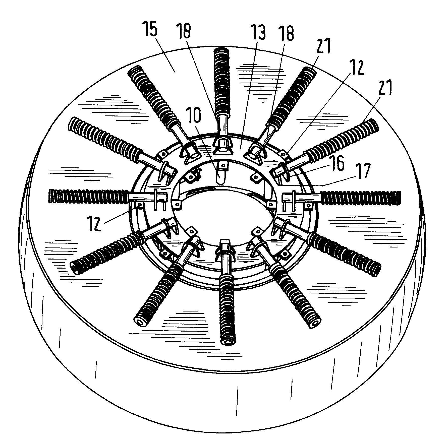
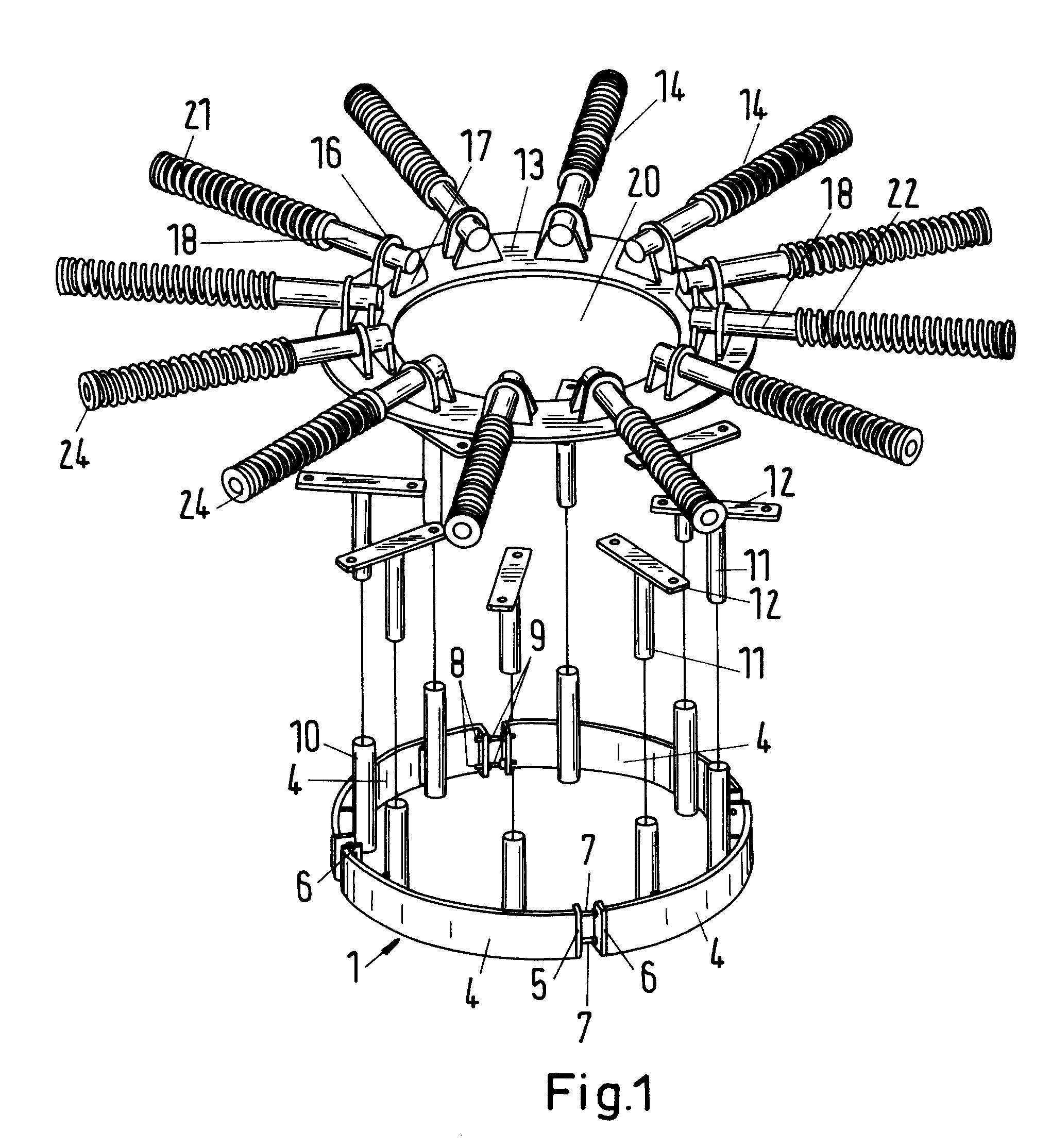
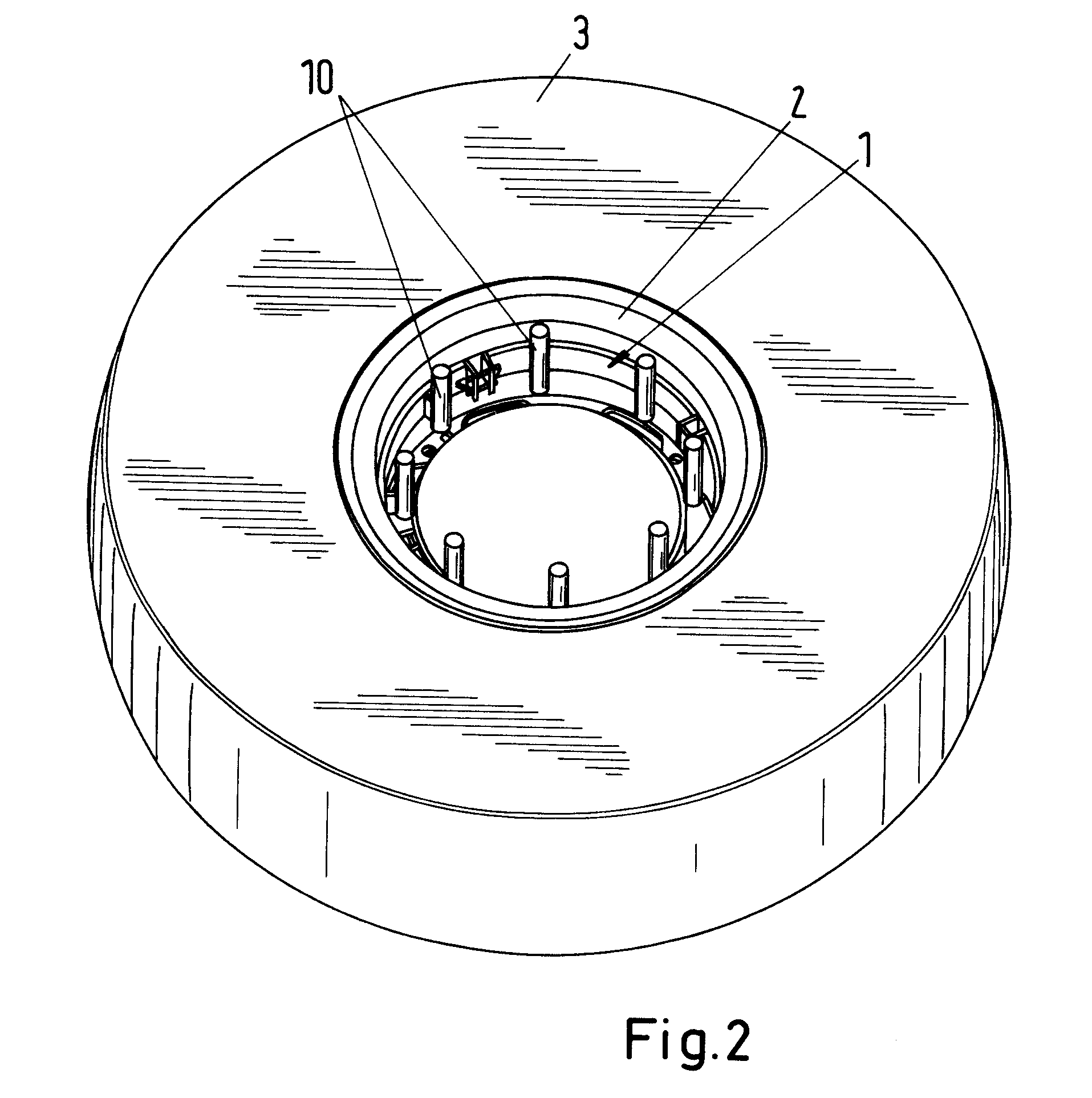
[0067]The protective device serves for protecting tire walls from damage and / or cuts caused by objects such as rocks, stones, scrap metal, slag, and the like. In this connection, the protective device is designed such that it does not have constant contact with the tire wall. In this way, the tire wall as well as the protective device are protected from premature wear. As will be explained in detail in the following with the aid of different embodiments, the protective device can be mounted or demounted, as needed, on the tire. In this way, the protective device must be mounted on the tire only when there is danger for the tire walls. The protective device is moreover advantageously designed such that it has no contact with the roadway or the ground so that the roadway cannot become damaged by the protective device. The components of the protective device are designed and arranged such that only in a critical situation they fulfill their function but otherwise do not exert any press...


PUM


Abstract

A protective device for tire walls has a holder for attaching the protective device on a wheel. The protective device has protective elements connected to the holder. The protective elements are shape-stable parts that under load are elastically deformable. They extend approximately radially away from the holder. The protective elements do not protect the entire tire but only the endangered area of the tire walls.

Description

BACKGROUND OF THE INVENTION[0001]The invention concerns a protective device for tire walls of vehicle tires that comprises at least one holder for attachment of the protective device on the wheel and further comprises protective elements.[0002]Depending on the ground across which the vehicles travel the tire walls are exposed to significant wear. The ground can comprise rocks, stones, scrap metal, slag or the like that cause significant load on the tire walls. Such unfavorable conditions occur for example on dumps where haul trucks, for example, dump trucks, travel. In such applications the tire walls are damaged within a short period of time and have cuts of such a kind that the tires must be changed. For protection of the tires protective tire chains are known that, however, are too complex for such applications. Moreover, such protective tire chains have a very great weight, are expensive, and are difficult to mount and demount. Also, protective tire chains are not suitable for v...

Claims


Application Information

Patent Timeline
IPC IPC(8): B60B7/01
CPCB60B7/01B60B7/12B60B7/063B60B7/04
Inventor RIEGER, HANSJORGRIEGER, JOHANNES WERNERBOGDAN, ZVONIMIR
Owner EISEN UND DRAHTWERK ERLAU AG
Why Eureka
Eureka Blog
Learn More