Rotation activated drum tuning system

a technology of rotating drums and drums, applied in the direction of percussion instruments, instruments, musical instruments, etc., can solve the problems of time-consuming and frustrating, time-consuming and skill-intensive pitching, etc., and achieve the effect of minimizing the contact area where the drums touch, maximum resonance, and mechanical advantag

Active Publication Date: 2009-03-10
SPINAZZOLA DAVID MICHAEL
View PDF2 Cites 27 Cited by
  • Summary
  • Abstract
  • Description
  • Claims
  • Application Information

AI Technical Summary

Benefits of technology

[0015]The new tuning system incorporates a means of grasping the rotating actuator ring by attaching a number of evenly spaced knob-like protrusions having a T shaped cross section to the outside diameter of the rotating actuator ring. A tool having a matching T shaped notch cut into it engages these knobs, which throughout this document will be referred to as radial cleats. This tool has a handle protruding out from it horizontally so that it can be grasped by a hand, or used as a leverage point to turn the rotating actuator ring on its axis. A plate referred to as the radius actuator grip plate is located below the rotating actuator ring and is attached to the camming mechanism and protrudes out from the drum shell. This radius actuator grip plate has a multiplicity of evenly spaced holes are around the size of most people's fingers in it radially so that at least one of the radial cleats will always be lined up with one of them. A drum stick for example could be used as a lever to provide additional mechanical advantage over what a person's hand can exert to turn the rotating actuator ring by inserting it into one of the holes in the radius actuator grip plate and pull against the tool which engages the closest radial cleats.
[0016]The new invention incorporates number of vertical tabs or brackets projecting upwards at the top horizontal surface of the rotating actuator ring and are evenly spaced and opposing each other and encircle its diameter. These vertical tabs or brackets have rollers mounted on axles facing inward so that these rollers ride on the horizontal flat of the inner ring or hoop rim which has a cross section shape of an L. The number of separate rollers which project inward from the vertical tabs on the rotating actuator ring that ride on the inner hoop minimizes the contact area where they touch and thereby allows for the maximum resonance when the drum head is struck, another improvement with this invention over its predecessor.
[0017]Due to the cylindrical shape of the drum shell and its relatively thin wall thickness, the common belief is less objects bolted to it as well as minimal contact area with the drum will provide better resonance when the drum is struck. Because of this, new lugs have been designed which have a very small footprint on the drum shell.
[0018]Due to the range of thicknesses of rims on drum head, being able to lift or lower the “camming mechanism” so that the musician may use a variety of different drum heads serves a very valuable function. A number of these lugs are evenly spaced around the outside diameter of the drum shell at its vertical surface at opposing points radially to evenly spread the load and securely attach the “camming mechanism” to the drum shell. This lug assembly design utilizes a cylindrical eccentric adjuster having an offset bolt or stud running through it horizontally and through the drum shell so it acts as a cam when rotated, which causes the lug assembly to move up or down, thereby raising or lowering the “camming mechanism”. This eccentric lug has an o-ring recessed in it and is compressed between the drum shell and itself, providing both grip for the eccentric to securely mate to the drum shell when attached as well as providing for isolation and maximum resonance.
[0019]Because the present invention utilizes new eccentric lugs, standard hoop mounting systems which suspend the drum does not fit correctly. To remedy this, a horizontal link having a horizontal threaded hole with a bolt protruding outward from the drum so that it can be supported by suspension mounting system. The suspension mount is semi circular in shape generally having a flat vertical cross section, several evenly spaced and opposing vertical holes have a grommet made of rubber or other flexible materials inserted into the hole to cushion the bolt that is inserted through it. This horizontal method for supporting the drum is designed to provide better isolation than vertically suspended drums by the simple fact that a very small surface area of the bolt actually touches the grommet in the hoop suspension mounting system. This isolation allows the drum to resonate freely and inhibits vibration from one drum from being transferred to another suspension mounted drum in the drum set.

Problems solved by technology

To evenly apply tension to the drum head to set the correct pitch takes a great amount of time and skill, often being time consuming and frustrating.

Method used


Image

  • Rotation activated drum tuning system
  • Rotation activated drum tuning system
  • Rotation activated drum tuning system

Examples


Embodiment Construction

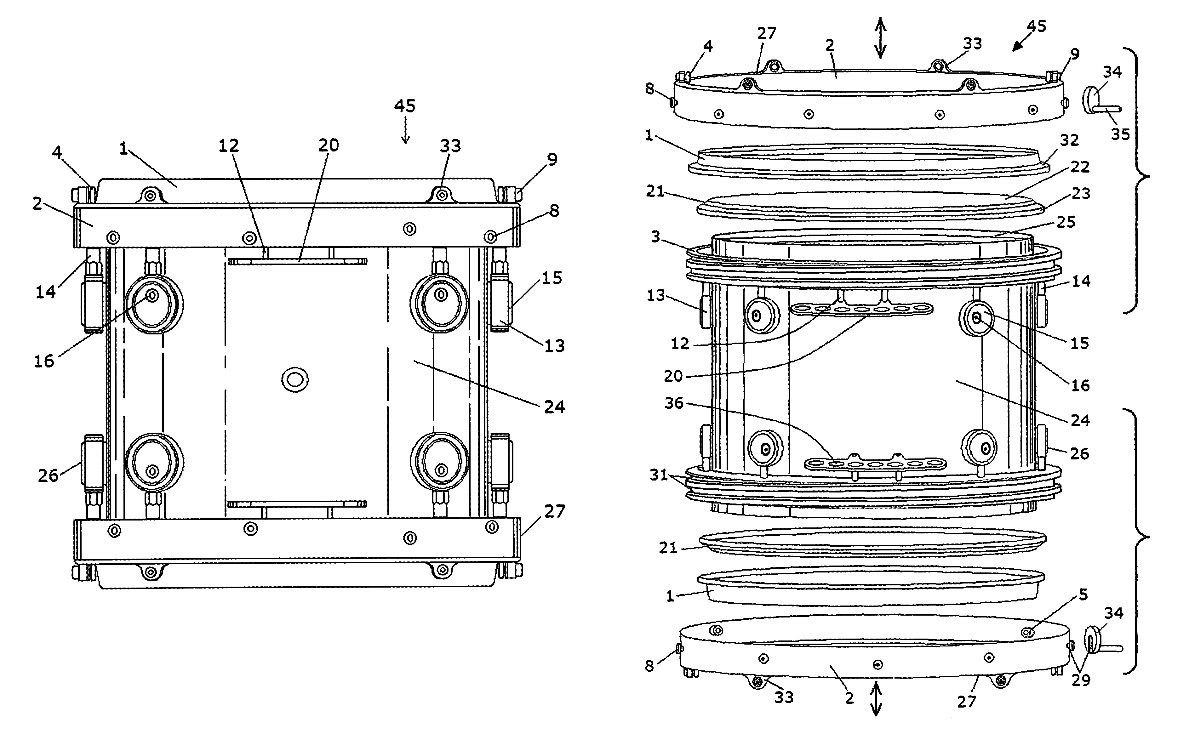
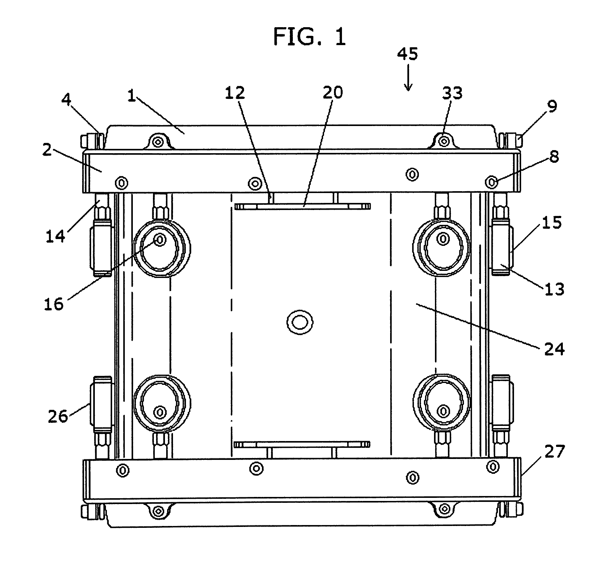
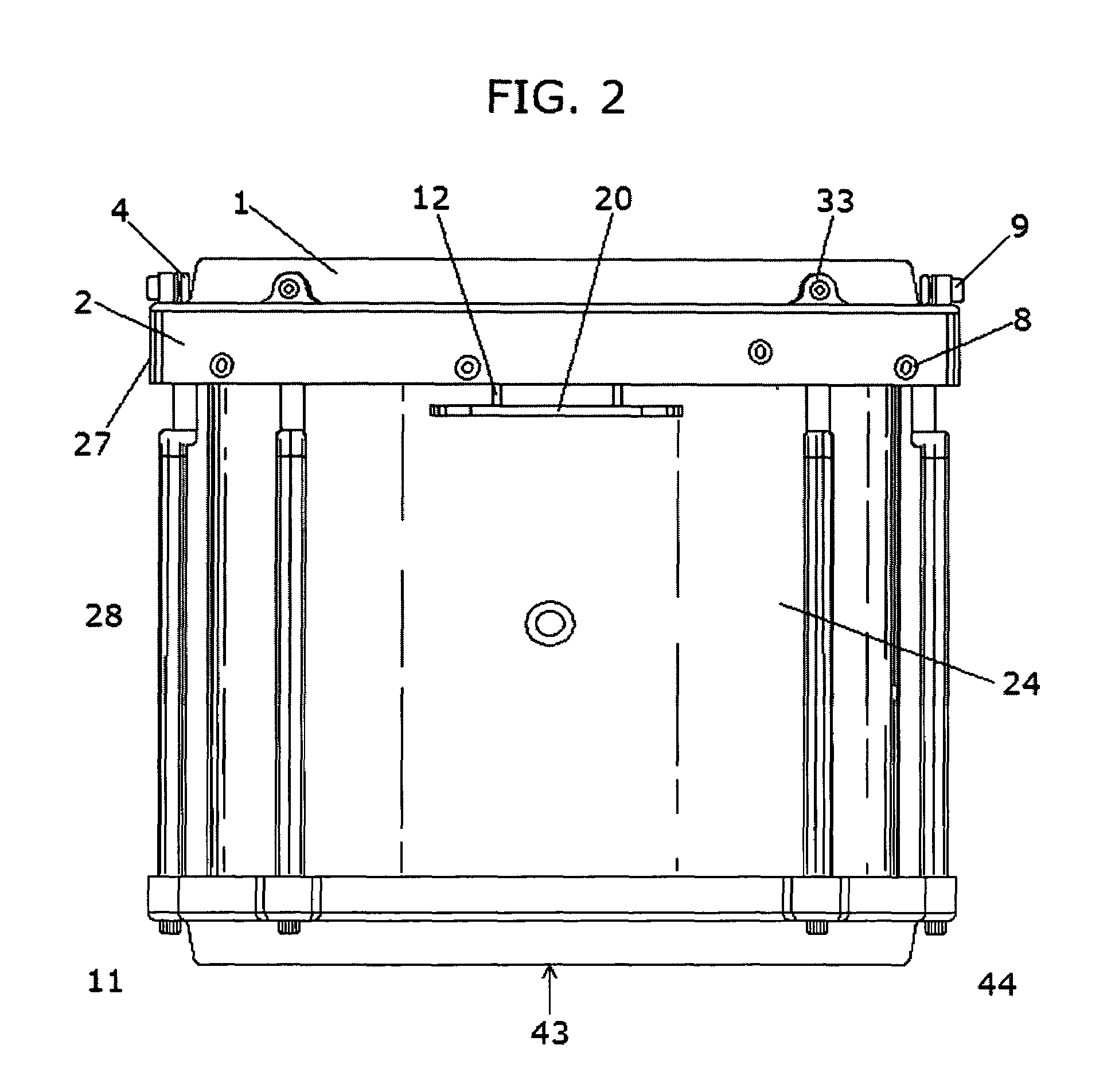
[0030]An embodiment of the invention as a whole is depicted in the drawings by reference character 45. An alternative embodiment of the invention as depicted in the drawings by reference character 43. The main components that make up the preferred embodiment of the invention are the counter hoop ring 1, rotating actuator ring assembly 27 which includes counter hoop rollers 4, radial cleats 8, rotating actuator ring rollers 5, spiral cam ring 3, eccentric lug assembly 26, radius actuator grip plate 20, actuator tool 34, and horizontal mounting assembly 42. As mentioned in the Summary of the invention, rollers 4, 5 imply wheels not excluding precision bearings and vice versa.

[0031]The present invention fully assembled is depicted in FIG. 1. The exploded view of FIG. 3 shows most all of the components that make up the drum 45 which includes a cylindrical drum shell 24 or body with opened ends 25 on each side, drum heads 21 enclosing both open ends 25, a cylindrical inner counter hoop 1...


PUM


Abstract

A drum tuning system which rotates clockwise or counterclockwise to adjust the tension of a drum head fitted over the open end of a drum body. It utilizes a rotating ring having numerous opposing equally spaced vertically projecting tabs along the top of the body's diameter, each with inward facing wheels that ride on the horizontal surface of a separate inner hoop bearing down on the drum head. The rotating actuator ring is fitted with multiple radial cleats projecting from its outside diameter for grasping it. A radius plate having horizontal holes extends from the drum body, and a tool engages the radial cleats on the rotating actuator ring to facilitate rotation. Multiple adjustable eccentric lugs are used to raise and lower the drum camming mechanism in relation to the open end of the drum body where attached. Horizontal projecting links support the drum attached to suspension mounting systems.

Description

CROSS REFERENCE TO RELATED APPLICATIONS[0001]U.S. Pat. Nos.6,043,419Aug. 26, 1980Arbiter4,218,952Mar. 28, 2000Arbiter5,739,448Apr. 14, 1998ToscanoD350,362Sep. 6, 1994FujiD339,818Sep. 28, 1993Peterson7,138,574Nov. 21, 2006Spinazzola4,295,405Oct. 20, 1981Sleishman4,448,105May 15, 1984Cordes4,570,526Feb. 18, 1986Hoshino4,619,179Oct. 28, 1986Wright4,714,002Dec. 22, 1987Cleland5,410,938May 2, 1995Kurosaki5,587,544Dec. 24, 1996Fuji6,166,311Dec. 26, 2000Barrickman6,417,432Jul. 9, 2002DowningD339,818Sep. 28, 1993PetersonD350,362Sep. 6, 1995FujiBACKGROUND OF THE INVENTION[0002]The present invention relates to a novel and useful apparatus for tuning an acoustic drum. Drums are comprised of several simple components including a drum head, most commonly made of a plastic material called Mylar, which include a rigid rim, generally made of a metallic material. The drum shell; most often made of layers of laminated wood, lexan plastic, aluminum, fiberglass or carbon fiber and formed to a cylindric...

Claims


Application Information

Patent Timeline
Patent Type & Authority Patents(United States)
IPC IPC(8): G10D13/02
CPCG10D13/023G10D13/02G10D13/16
Inventor SPINAZZOLA, DAVID MICHAEL
Owner SPINAZZOLA DAVID MICHAEL
Why Eureka
Try Eureka