Display device with touch screen

a display device and touch screen technology, applied in the field of display devices with touch screens, can solve the problems of reducing sensitivity, touch screen on display, reducing sensitivity, etc., and achieve the effect of increasing the sensitivity of the touch screen

Active Publication Date: 2010-03-11
INNOLUX CORP
View PDF7 Cites 49 Cited by
  • Summary
  • Abstract
  • Description
  • Claims
  • Application Information

AI Technical Summary

Problems solved by technology

One unavoidable feature of touch screens on displays is that one set of the orthogonal electrodes will be close to an electrical ground plane within the display itself.
This tends to reduce the sensitivity, as the ground plane “attracts” electric field lines that would otherwise extend out of the device, these field lines cannot therefore be influenced by touching the screen resulting in the reduced sensitivity.

Method used


Image

  • Display device with touch screen
  • Display device with touch screen
  • Display device with touch screen

Examples


Embodiment Construction

[0032]It is to be understood that the following disclosure provides many different embodiments, or examples, for implementing different features of various embodiments. Specific examples of components and arrangements are described below to simplify the present disclosure. These are merely examples and are not intended to be limiting.

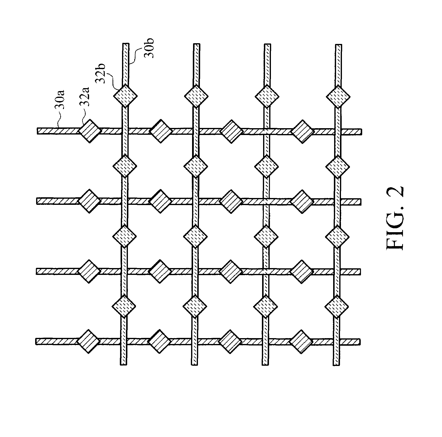
[0033]The invention provides an arrangement of the electrodes of a touch sensor structure in which the two electrode arrays occupy different fractions of the touch sensor area. This is termed an “asymmetric” electrode design, in which different electrode arrays have different fill factors. The advantage of improved sensitivity is explained below.

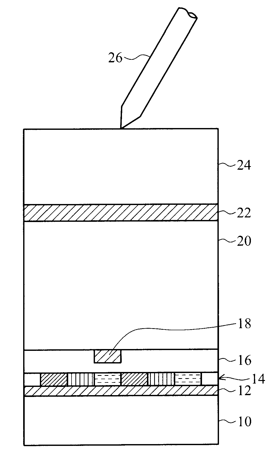
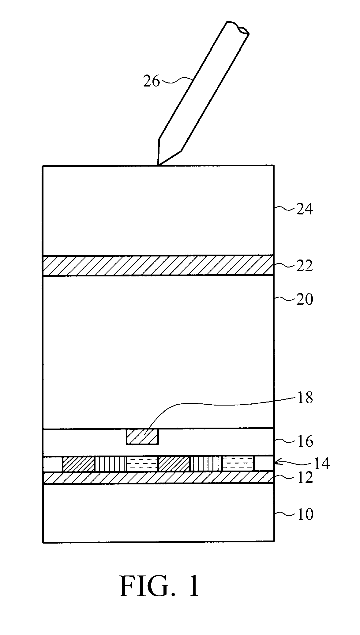
[0034]FIG. 1 shows one example of known layer structure for a display device with capacitance touch sensor input and to which the invention can be applied.

[0035]Part of the display is shown, and this includes at least a display layer. The precise design of display panel is not material to the invention, and for ...


PUM


Abstract

A display device with touch sensor input has a touch sensor structure on top of the display layer. The touch sensor structure includes a first and second array of electrodes, the electrodes in the first array being non-parallel to the electrodes in the second array. The first and second arrays of electrodes occupy different fractions of a touch sensor area. These asymmetric fill factors give improved sensitivity.

Description

CROSS-REFERENCE TO RELATED APPLICATIONS[0001]This application claims the benefit of U.S. Provisional Application No. 61 / 125,962 filed on Apr. 30, 2008, the entirety of which is incorporated herein by reference.[0002]This application claims the benefit of European Patent Application No. 08164078.1 filed on 10 Sep. 2008, the entirety of which is incorporated herein by reference.BACKGROUND OF THE INVENTION[0003]1. Field of the Invention[0004]This invention relates to display devices with touch screens.[0005]2. Description of the Related Art[0006]Touch screens are becoming increasingly common in consumer electronics applications where an LCD display is present in a device e.g. mobile phone, PDA or camera. User interaction via a touch screen saves the space required for key inputs and therefore allows a larger display area for a given size of device.[0007]Of the possible physical effects used to locate the “touched” position on such a screen, sensing the capacitance change induced betwee...

Claims


Application Information

Patent Timeline
Patent Type & Authority Applications(United States)
IPC IPC(8): G06F3/041
CPCG06F3/044G02F1/13338G02F1/1343G06F3/0412G06F3/0445G06F3/047G06F3/04144G02F1/133514
Inventor WHIGHT, KENNETH R.
Owner INNOLUX CORP
Why Eureka
Try Eureka