Wire fault illumination and display

a fault illumination and display technology, applied in the field of data processing systems, can solve the problems of complex systems, tens of miles of wiring, and modern aircraft, and achieve the effects of reducing the difficulty of users using these types of schematic diagrams, time-consuming and labor-intensiv

Active Publication Date: 2010-03-11
THE BOEING CO
View PDF33 Cites 44 Cited by
  • Summary
  • Abstract
  • Description
  • Claims
  • Application Information

AI Technical Summary

Problems solved by technology

Complex systems, such as modern aircraft, may have tens of miles of wiring.
The use of these types of schematic diagrams may be...

Method used


Image

  • Wire fault illumination and display
  • Wire fault illumination and display
  • Wire fault illumination and display

Examples


Embodiment Construction

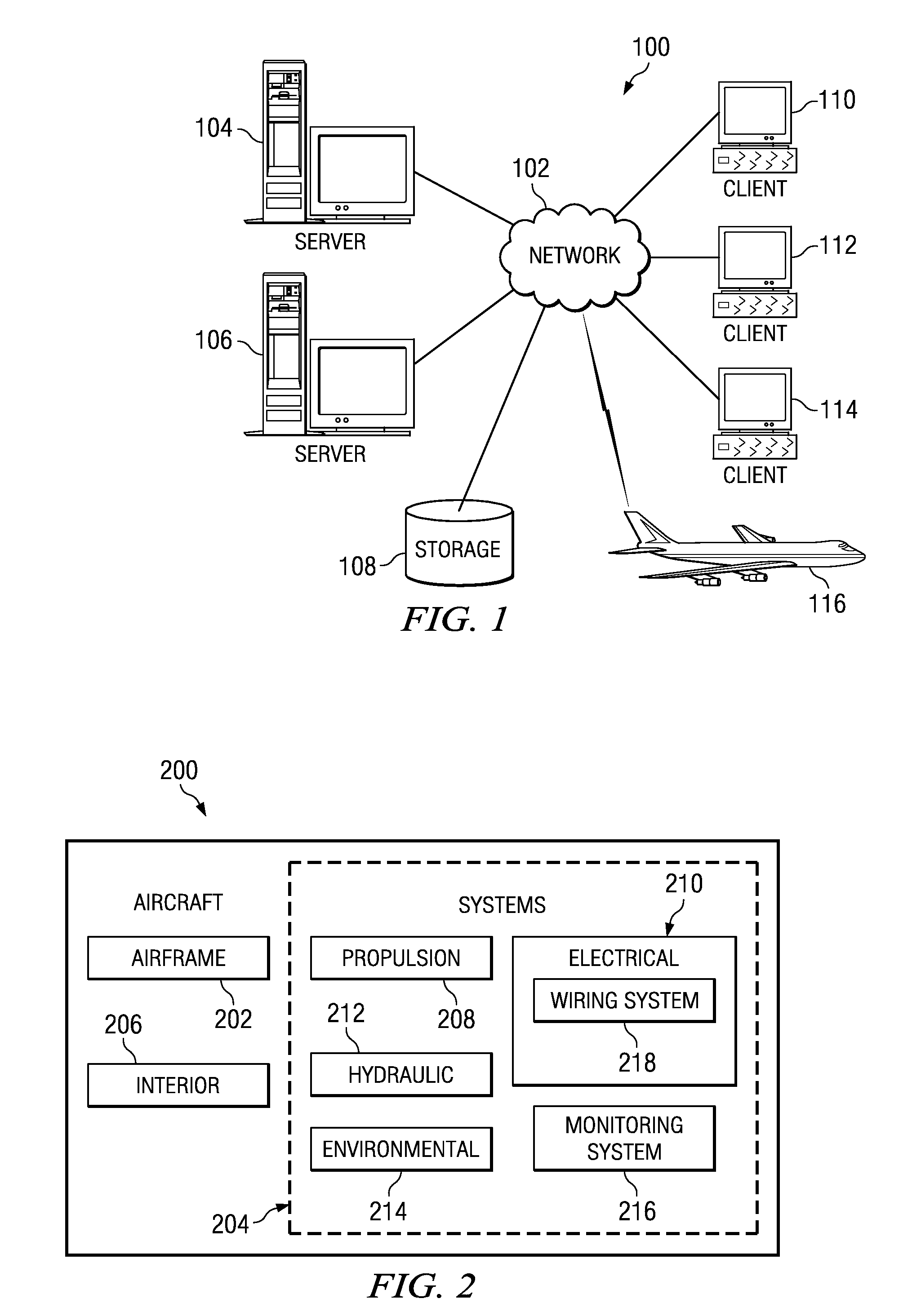
[0028]With reference now to the figures and in particular with reference to FIG. 1, an exemplary diagram of a data processing environment is provided in which the advantageous embodiments may be implemented. It should be appreciated that FIG. 1 is only exemplary and not intended to assert or imply any limitation with regard to the environment in which different embodiments may be implemented. Many modifications to the depicted environments may be made.

[0029]FIG. 1 depicts a pictorial representation of a network of data processing systems in which the advantageous embodiments may be implemented. Network data processing system 100 is a network of computers in which embodiments may be implemented. Network data processing system 100 contains network 102, which is the medium used to provide communications links between various devices and computers connected together within network data processing system 100. Network 102 may include connections, such as wire, wireless communication links...


PUM


Abstract

A computer implemented method, apparatus, and computer usable program product for illuminating faults in a wiring system. The wiring system is monitored for a fault during operation of the wiring system. In response to detecting the fault, a location of the fault within the wiring system is estimated. A wiring diagram is presented for the wiring system with an indication of the location of the fault within the wiring system.

Description

BACKGROUND INFORMATION[0001]1. Field[0002]The present disclosure relates generally to an improved data processing system and in particular to a method and apparatus for illuminating faults in a wiring system. Still more particularly, the present disclosure relates to a computer implemented method, apparatus, and computer usable program code for displaying wiring faults in a wiring system.[0003]2. Background[0004]Complex systems, such as modern aircraft, may have tens of miles of wiring. Wires are used to distribute power and / or data to various types of devices in an aircraft. Diagrams illustrating representations of these systems are referred to as schematic diagrams. A schematic diagram may identify the connections and interactions between various devices. The connections between devices, providing flow for power and / or data, are referred to as paths. A path may include any component that connects to a device. These systems of connections and devices may be referred to as wiring sy...

Claims


Application Information

Patent Timeline
IPC IPC(8): G01R31/28
CPCG01R31/088G01R31/086
Inventor THOMAS, TERRANCE L.BOOSE, JOHN HENRY
Owner THE BOEING CO
Why Eureka
Try Eureka