
Roller type adjustable screen fixing apparatus

a fixing apparatus and roller-type technology, applied in the direction of scaffold accessories, curtain suspension devices, instruments, etc., can solve the problems of prior art that is not cost-effective, environmental problems for disposal, waste, etc., and achieve the effect of better economic benefits

Inactive Publication Date: 2010-03-18
PORTWELL
View PDF20 Cites 21 Cited by
  • Summary
  • Abstract
  • Description
  • Claims
  • Application Information

AI Technical Summary

Benefits of technology

[0006]Therefore, it is a primary objective of the present invention to provide a roller type adjustable screen fixing apparatus extended or contracted from the periphery of the fixing base to fit screens of different sizes, and cover a larger range of generality to prevent the manufacturing and inventory issues of fixing bases of different sizes, so as to give better economic benefits to its manufacture.
[0007]Another objective of the present invention is to provide a roller type adjustable screen fixing apparatus capable of changing a screen of a different size conveniently and adjusting the screen dynamically, so as to provide better economic benefits to its use.

Problems solved by technology

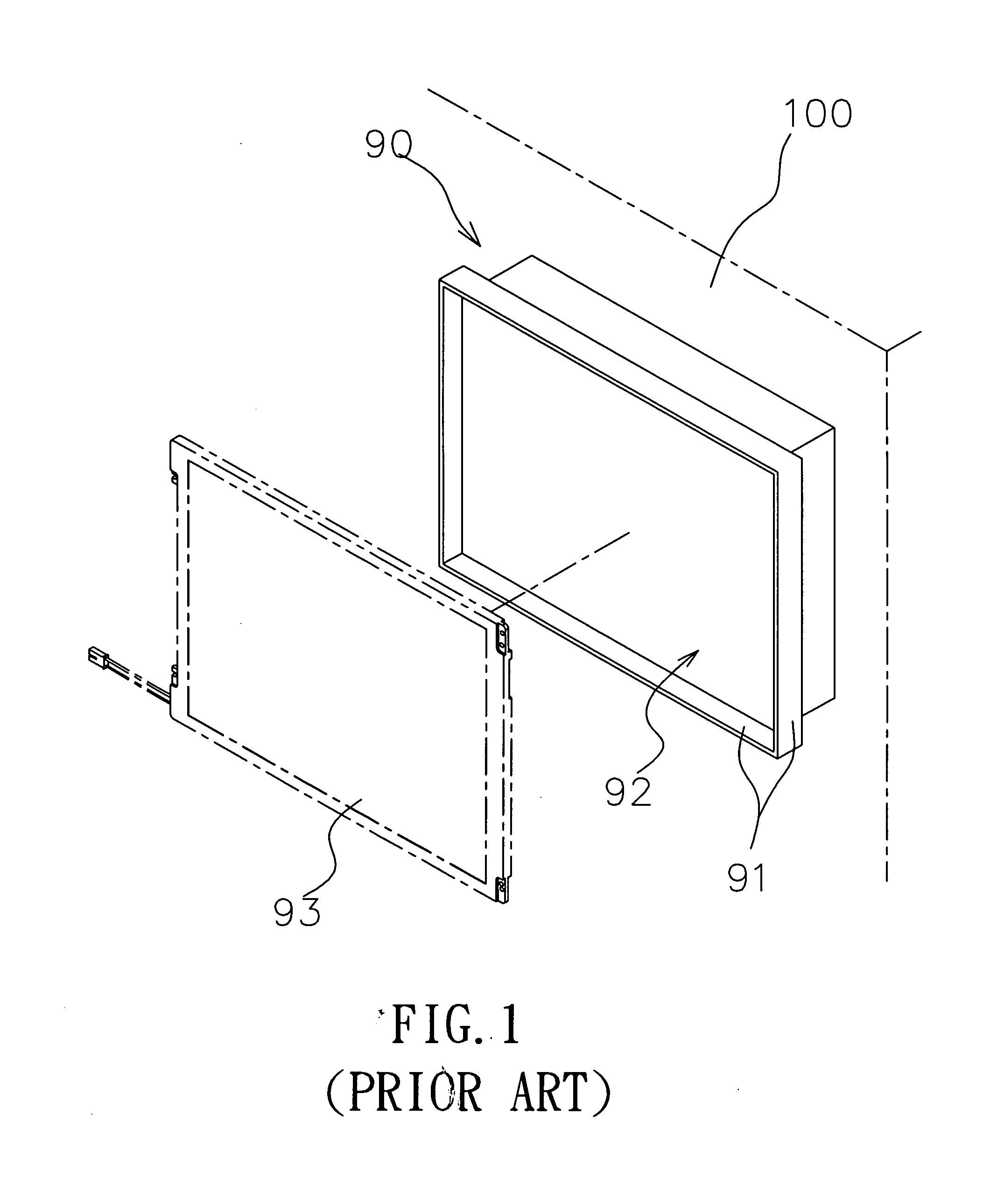
Although the fixing base 90 can achieve the effect of containing and positioning the screen 93, there are drawbacks, such as if the area or size of the screen 93 cannot meet the actual need and the fixing base 90 no longer can be used, it is necessary to exchange or expand the screen 93, or else the fixing base 90 will become a waste.
The prior art is not cost-effective, or even causes an environmental issue for the disposal.
Obviously, the design of the structure of the conventional screen fixing base is not good enough.

Method used


Image

  • Roller type adjustable screen fixing apparatus
  • Roller type adjustable screen fixing apparatus
  • Roller type adjustable screen fixing apparatus

Examples


Embodiment Construction

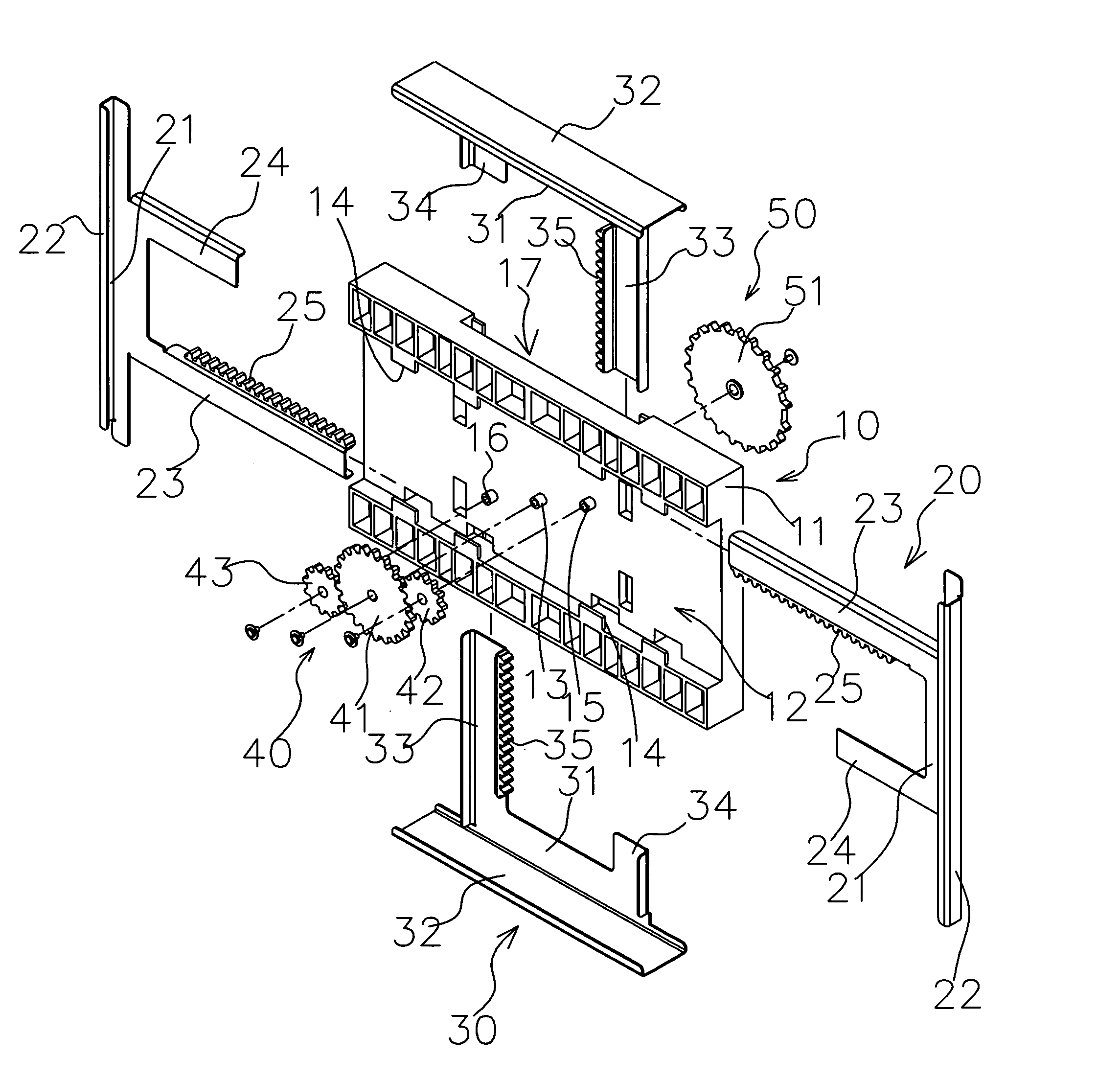
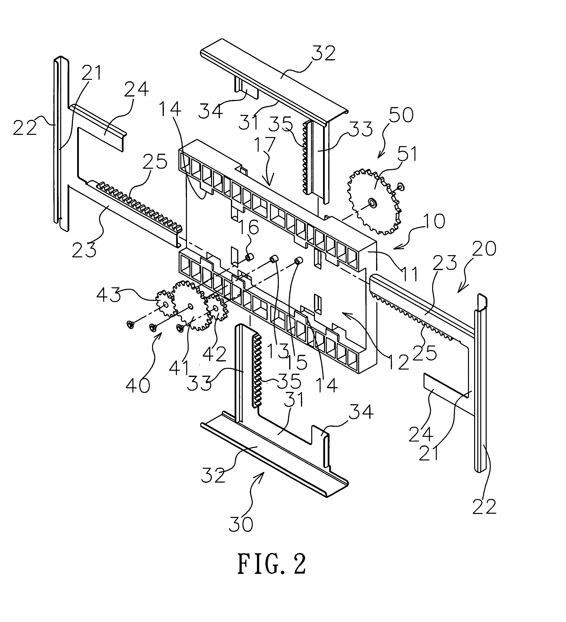
[0017]With reference to FIGS. 2 and 3, a roller type adjustable screen fixing apparatus of the invention comprises: a fixing apparatus 10, a first distal plate device 20, a second distal plate device 30, a first linking device 40 and a second linking device 50, wherein the fixing apparatus 10 includes a fixing base 11 substantially in the shape of a plate, and having a transversal concave operating slot 12 at the middle of a side (a front side); the operating slot 12 includes a central positioning pillar 13 disposed at the middle of the operating slot 12, and both sides of the central positioning pillar 13 have a lateral positioning pillar 15, 16 each, and the lateral positioning pillars 15, 16 are generally not aligned on the same line and come with a slight height difference. In addition, both left and right sides of the fixing base 11 include a serrated press plate 14 disposed separately at a position corresponding to a connecting position of the corresponding operating slot 12 a...


PUM


Abstract

A roller type adjustable screen fixing apparatus includes: a fixing base, having at least one operating slot; at least one distal plate device disposed at an external side of the distal plate, having at least two distal plates embedded in the operating slot, and slidably moving in the operating slot, and a frame plate disposed at an external side of the distal plate; at least one linking device, having at least one roller installed in the operating slot and linked with the distal plate; and a containing space, defined by the upper frame plates of the corresponding distal plates for installing a screen. The distal plate is contractible in the operating slot for adjusting the containing space, such that the invention can fit screens of different sizes, and provide a convenient replacement and a dynamic adjustment.

Description

BACKGROUND OF THE INVENTION[0001]1. Field of the Invention[0002]The present invention relates to a roller type adjustable screen fixing apparatus, and more particularly to a screen fixing apparatus flexibly installed around the periphery of a screen for changing the size and form of the screen to provide a very convenient and cost-effective apparatus with an easy and efficient installation.[0003]2. Description of the Related Art[0004]Electronic multimedia is generally used for advertising, and screen becomes a mainstream of such electronic advertising with dynamic multimedia audio / video effects. With reference to FIG. 1 for a structure of a conventional screen fixing base, the screen fixing base comprises: a fixing base 90, having a frame 91 and an embedding space 92 defined by the frame 91. When the structure is used, the fixing base 90 is mounted onto or embedded into a wall 100, and a screen 93 is installed and fixed at an embedding space 92 of the fixing base 90, such that the s...

Claims


Application Information

Patent Timeline
Patent Type & Authority Applications(United States)
IPC IPC(8): F16M13/00G03B21/58
CPCG03B21/58F16M13/02
Inventor LIU, KUN-PEI
Owner PORTWELL
Learn More