
Cutter of a juicer

a juicer and juicer technology, applied in the field of juicer cutter, can solve the problems of comparatively large dregs and inability to thoroughly crush vegetables and fruits, and achieve the effect of quick and evenly cutting and crushing vegetables and fruits

Inactive Publication Date: 2010-03-25
LIN KUAN CHIH
View PDF10 Cites 31 Cited by
  • Summary
  • Abstract
  • Description
  • Claims
  • Application Information

AI Technical Summary

Benefits of technology

[0005]The objective of this invention is to offer the cutter of a juicer, able to quickly and evenly cut and crush vegetable and fruit into juice.

Problems solved by technology

Thus, the vegetable and fruit can hardly be crushed thoroughly, likely to leave comparatively big dregs.

Method used


Image

  • Cutter of a juicer
  • Cutter of a juicer
  • Cutter of a juicer

Examples


Embodiment Construction

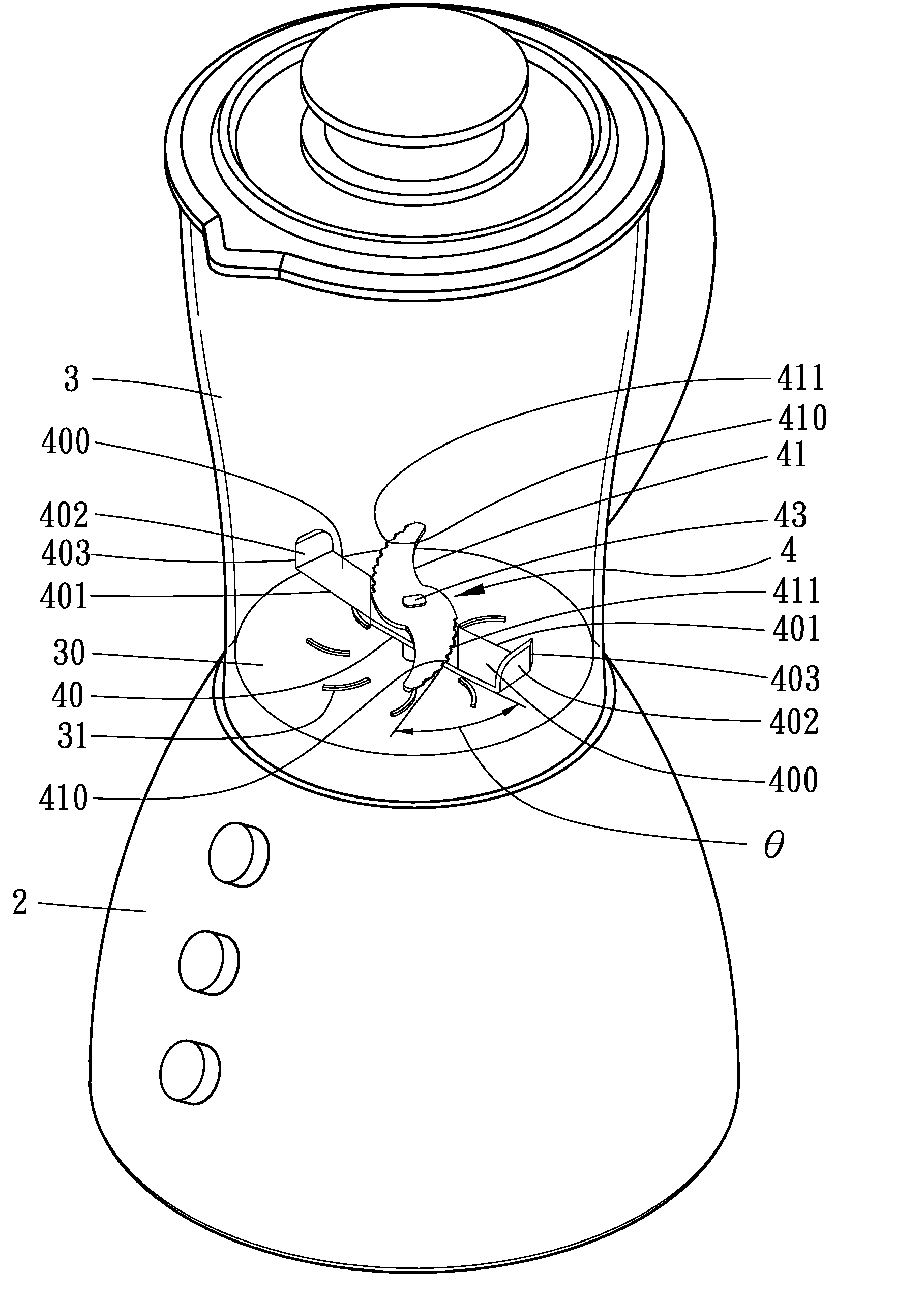
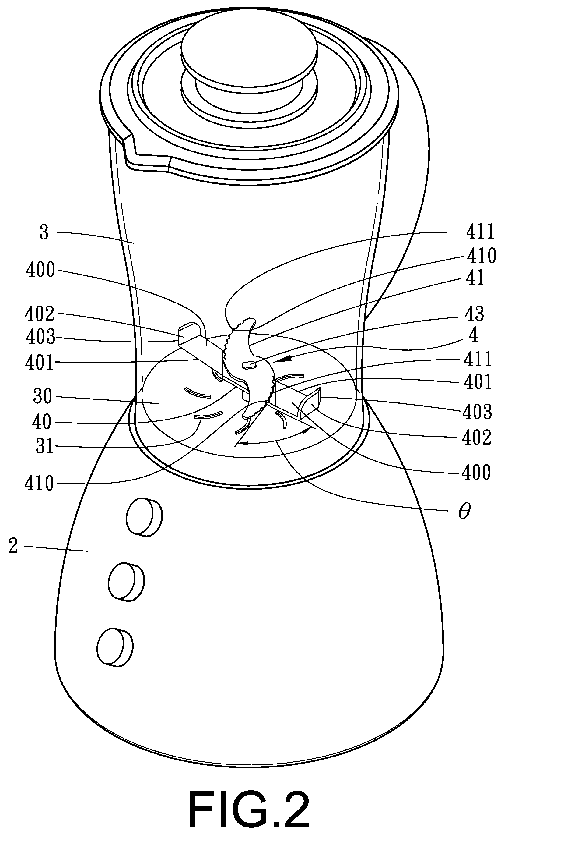
[0017]A first preferred embodiment of the cutter of a juicer in the present invention, as shown in FIGS. 2˜5, includes a base 2, a bowl 3 and a cutter set 4 combined together.

[0018]The base 2 is provided therein with a motor and a correlative circuit and mechanism (not shown), which are the transmission mechanism installed in the interior of a common juicer.

[0019]The bowl 3 is to be movably assembled on the base 2, having its inner lower side 30 disposed thereon with a plurality of eddy-shaped projecting bars 31.

[0020]The cutter set 4 is installed on the bottom 30 of the bowl 3, provided with a first cutter 40 and a second cutter 41. The first cutter 40 has its opposite ends respectively slanting to one side of the diagonal edges and forming a little upturned cutting member 400. The two cutting members 400 at the opposite ends of the first cutter 40 have their diagonal edges respectively formed with a cutting edge 401 and their outer ends respectively bent upward to form a flow-guid...


PUM


Abstract

The cutter of a juicer includes a cutter set provided with a first cutter and a second cutter. The first cutter has its opposite ends respectively slanting to one side of the diagonal edges and forming an upward cutting member having their diagonal edges respectively formed with a cutting edge and their outer ends respectively bent upward to form a flow-guiding wall with a cutting edge at a diagonal edge. The second cutter is S-shaped and positioned over the first cutter, having the diagonal edges of its opposite sides respectively provided with a cutting edge. The first and the second cutter are secured on a rotating shaft, and an included angle between the first and the second cutter is less than 60 degrees. Vegetable and fruit can quickly and evenly be cut and crushed into juice by the cutter set rotating at high speed.

Description

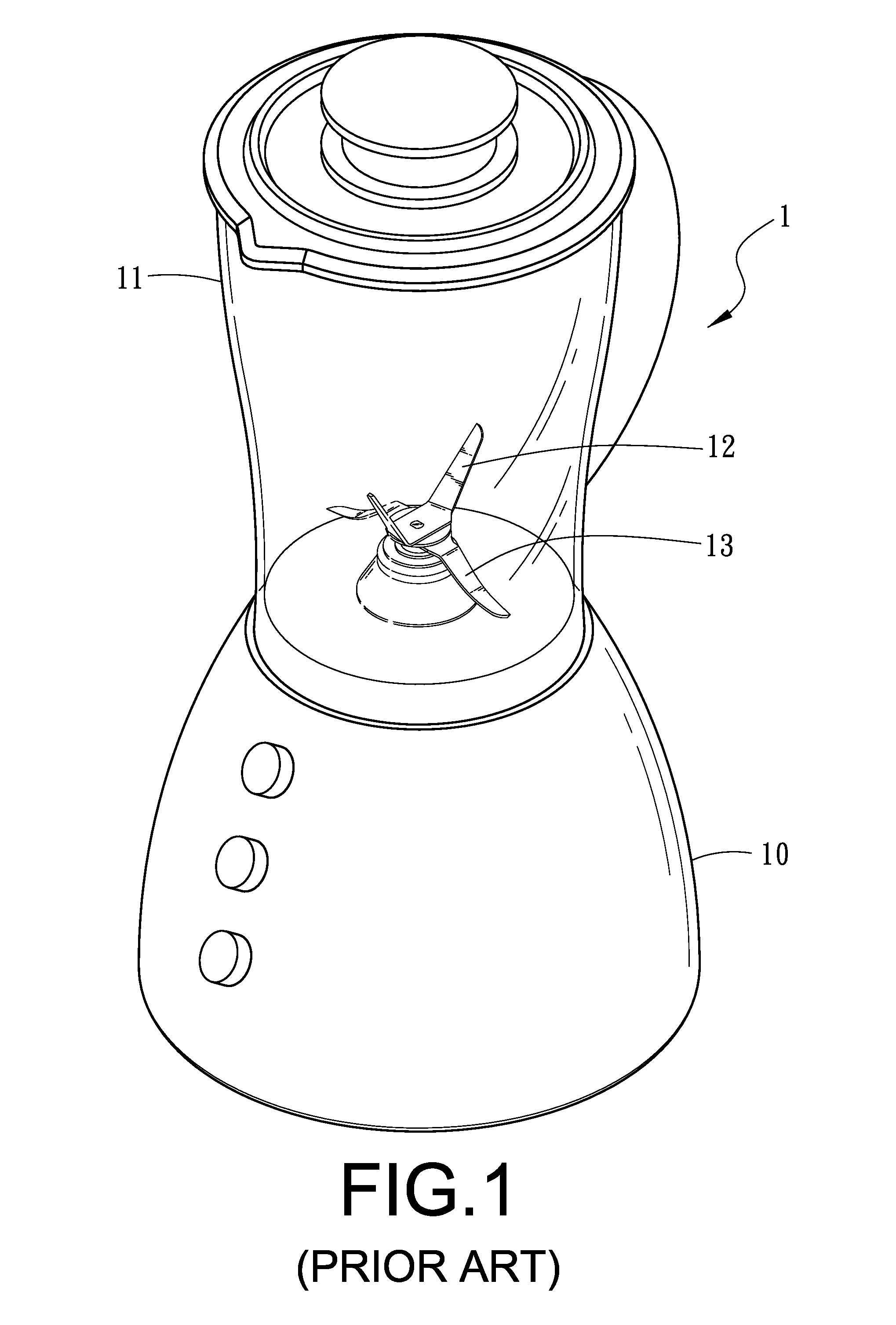
BACKGROUND OF THE INVENTION[0001]1. Field of the Invention[0002]This invention relates to the cutter of a juicer, particularly to one provided with a cutter set driven to rotate and able to quickly and evenly crush and stir vegetable and fruit into juice.[0003]2. Description of the Prior Art[0004]A conventional juicer 1, as shown in FIG. 1, includes a base 10, a bowl 11 movably assembled on the base 10, an upper cutter 12 and a lower cutter 13 combined together. The upper cutter 12 bent upward and the lower cutter 13 bent downward are positioned in the interior of the bowl 11. The base 10 is installed therein with a motor and a correlative circuit and mechanism to drive the upper cutter 12 and the lower cutter 13 in the bowl 11 to rotate for cutting and crushing the vegetable and fruit in the bowl 11. However, the upper cutter 12 and the lower cutter 13 of the conventional juicer 1 are positioned perpendicularly to each other and respectively bent upward and downward, and the inner ...

Claims


Application Information

Patent Timeline
Patent Type & Authority Applications(United States)
IPC IPC(8): B02C18/18B02C18/08
CPCA47J43/0722
Inventor LIN, KUAN-CHIH
Owner LIN KUAN CHIH
Learn More