Stock assembly with recoil suppression

a technology of recoil suppression and stock assembly, which is applied in the direction of weapon components, butts, weapons, etc., can solve the problems of reducing the accuracy of firing shotguns, not only painful to the user, and achieve the effect of strengthening the connection and reducing the risk of breakag

Active Publication Date: 2010-03-25
PHOENIX TECHNOLOGIES LTD
View PDF21 Cites 73 Cited by
  • Summary
  • Abstract
  • Description
  • Claims
  • Application Information

AI Technical Summary

Benefits of technology

[0016]The connector tube may include a protective cover extending forward of the tube and partly over the attachment member when the attachment member is in the fully extended position and fully over exposed area of the attachment member and above a part of the pistol grip when the recoil suppressor is compressed, thereby preventing pinching of the user's cheek between the forward end of the tube and the pistol grip.
[0029]When the shotgun is fired, the shotgun and pistol grip move rearwardly, pressing the attachment member into the cylinder, and thereby compressing the spring which absorbs the force of the recoil. As a result, the impact of the rear of the stock, normally covered by a recoil pad, not shown, is substantially reduced. After firing, the spring decompresses to urge the retainer forward in preparation for the next shot. Positioning of the connector tube and pistol grip connector along an axis parallel to the longitudinal axis of the connector tube significantly strengthens the connection and reduces the risk of breakage due to the shotgun recoil.

Problems solved by technology

While these replacement stock assemblies improve handling and aesthetics, prior art stock assemblies can break or detach at the connection of the connector tube to the pistol grip, and do not reduce recoil or “kick” when firing the shotgun, which is not only painful to the user, but also reduces accuracy in firing the shotgun.

Method used


Image

  • Stock assembly with recoil suppression
  • Stock assembly with recoil suppression
  • Stock assembly with recoil suppression

Examples


Embodiment Construction

[0037]In the following description, terms such as horizontal, upright, vertical, above, below, beneath, and the like, are used solely for the purpose of clarity in illustrating the invention, and should not be taken as words of limitation. The drawings are for the purpose of illustrating the invention and are not intended to be to scale.

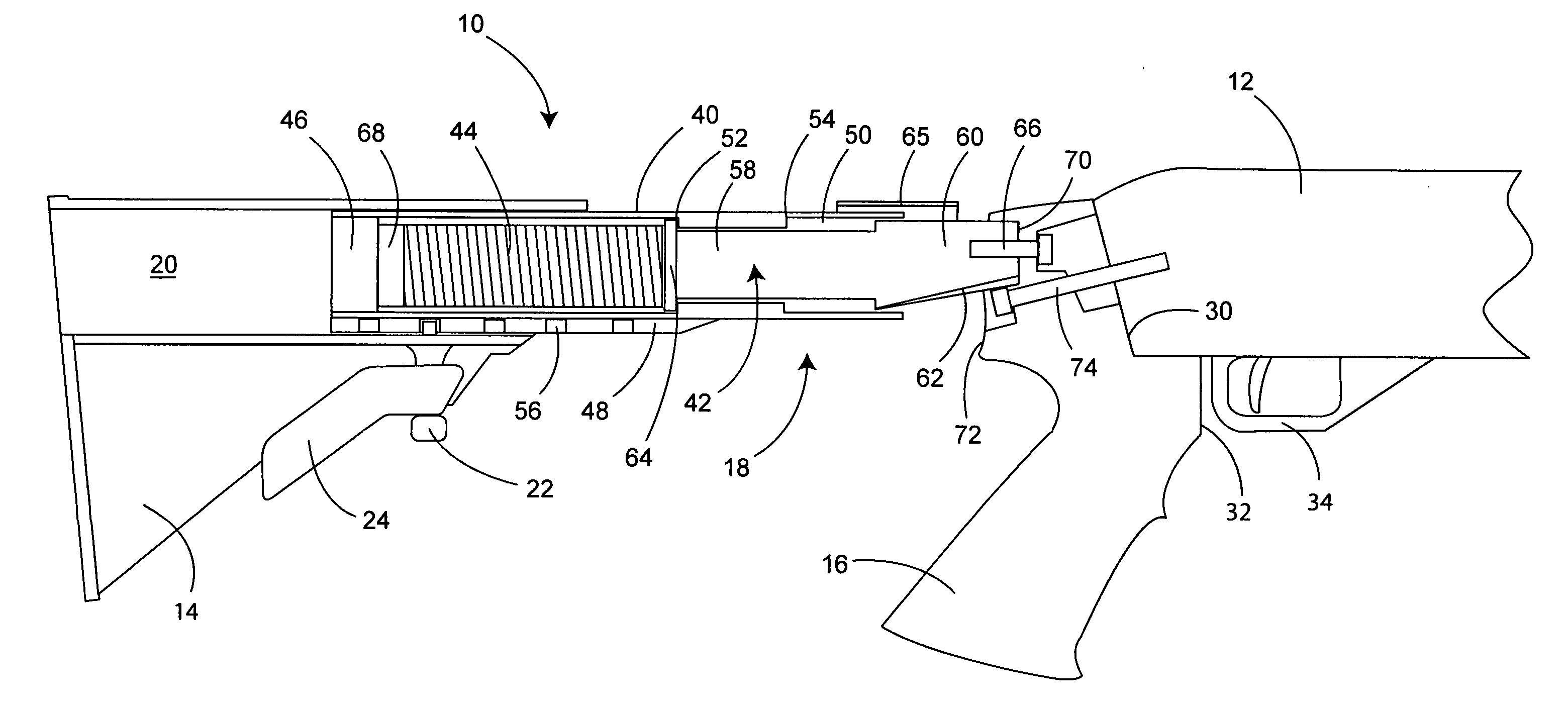
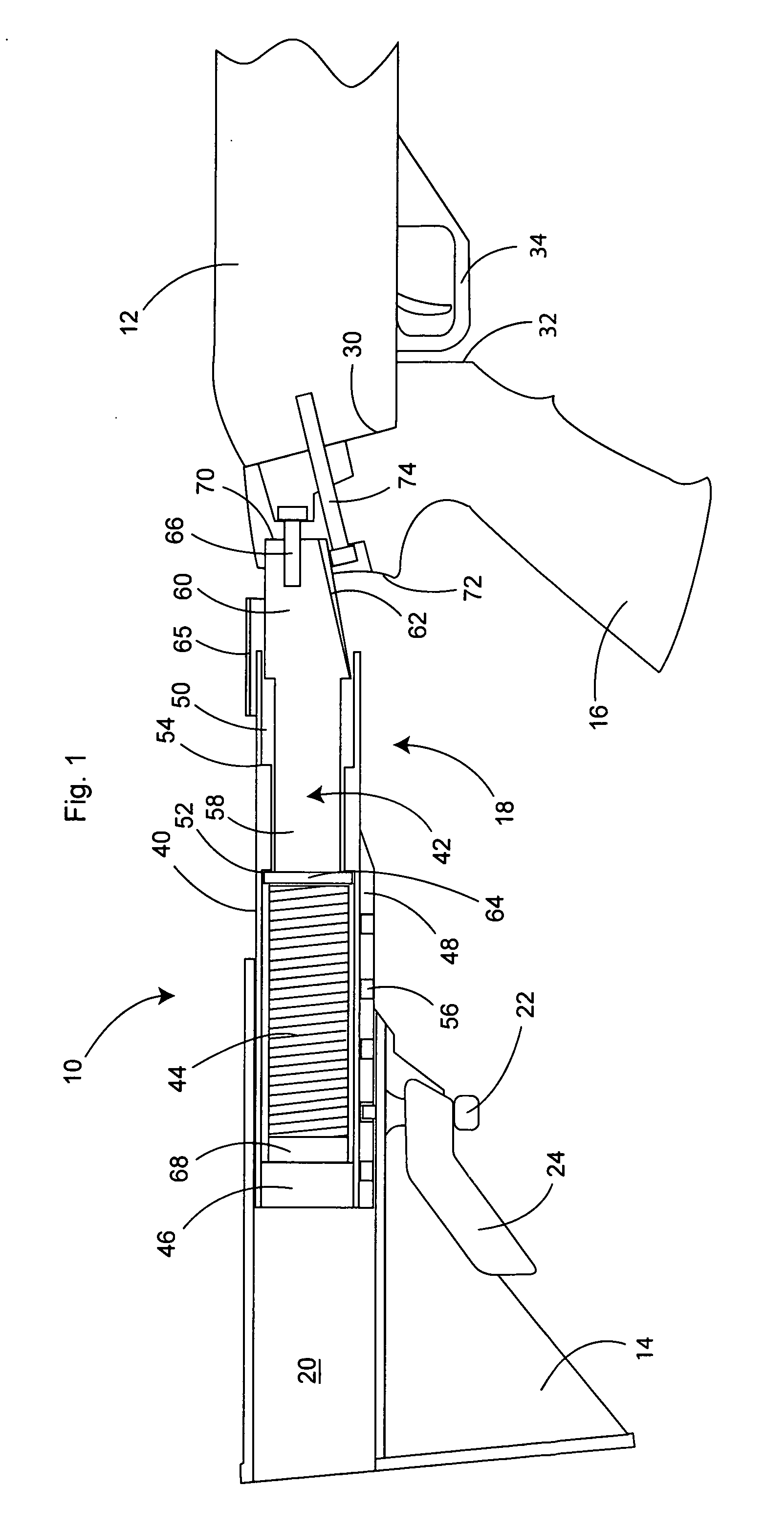
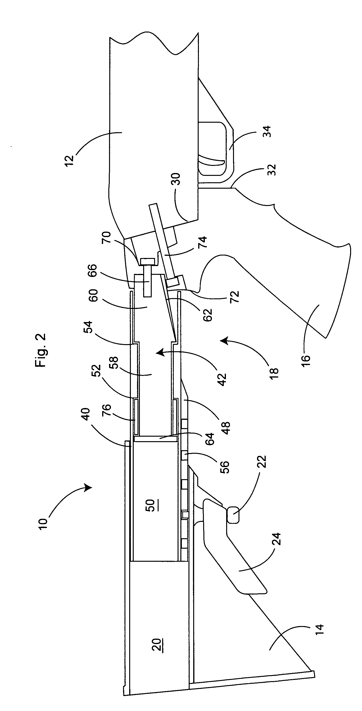
[0038]FIG. 1 illustrates a sectional side view of a preferred embodiment of the stock assembly incorporating recoil suppression, generally 10, attached to shotgun receiver 12. The major components of stock assembly 10 are buttstock 14, pistol grip 16 and recoil connector assembly, generally 18.

[0039]Buttstock 14, which is preferably molded from an impact and scuff-resistant polymer, includes conduit 20 extending from the front to the rear of buttstock 14 to slidably receive connector assembly 18. Retractable latch pin 22 is mounted on buttstock 14 perpendicular to the longitudinal axis of conduit 20. Pin 22 is urged by a spring, not shown, to an exte...


PUM


Abstract

A stock assembly for attachment to the receiver of a shotgun is described. The assembly includes a pistol grip; a stock; a connector tube slidable within a conduit in the stock, the stock and connector being selectively lockable to each other; an attachment member slidable within the tube conduit between fully inserted and fully extended positions; a first elongated connector attached to the attachment member and extending parallel to the longitudinal axis of the tube into attachment with the pistol grip; a second elongated connector extending from the pistol grip into engagement with the receiver, the second member being at an angle to the first member; and a compression spring in the tube conduit urging the attachment member toward its fully extended position.

Description

[0001]This application claims the priorities of U.S. Provisional Appl. Ser. No. 61 / 192,840 filed Sep. 22, 2008, and U.S. Provisional Appl. Ser. No. 61 / 203,894 filed Dec. 30, 2008, the entire disclosures of which are incorporated herein by reference.BACKGROUND OF THE INVENTION [0002](1) Field of the Invention[0003]The present invention relates generally to a stock assembly for use on a shotgun, and in particular to a stock assembly to replace the original shotgun stock having a more break-resistant means of receiver attachment and a means for recoil suppression.[0004](2) Description of the Prior Art[0005]Shotgun owners often replace the original shotgun stock, or buttstock, with a replacement stock assembly to provide improved handling and control, or simply for aesthetic purposes. These replacement stock assemblies are comprised of a pistol grip, a buttstock, and a connector tube to join the buttstock to the pistol grip in designs where the pistol grip and buttstock are not integral...

Claims


Application Information

Patent Timeline
Patent Type & Authority Applications(United States)
IPC IPC(8): F41C23/20F41C23/00F41C23/04
CPCF41C23/04F41C23/00F41C23/14F41C23/06
Inventor VESLIGAI, ZELJKO
Owner PHOENIX TECHNOLOGIES LTD
Why Eureka
Try Eureka