
Monolithic concrete wall expansion joint system

a technology of expansion joints and monolithic concrete, which is applied in the field of monolithic concrete wall expansion joints, can solve the problems of increasing the price of the project, requiring additional labor costs, and reducing so as to reduce the amount of labor and time to construct, and mitigate against crack formation.

Active Publication Date: 2010-03-25
SHAW & SONS
View PDF31 Cites 1 Cited by
  • Summary
  • Abstract
  • Description
  • Claims
  • Application Information

AI Technical Summary

Benefits of technology

"The wall expansion joint system described in this patent is designed to prevent cracks in concrete walls and minimize color variations between segments. It allows for the separation of large concrete walls into smaller segments, saving time and reducing labor. The system includes a rigid plate and a compressible material between the concrete wall components, which permits contraction and expansion without imposing significant stresses on the components. The system also allows for the same concrete mix to be used for all segments, reducing color variations. Overall, the system improves the quality and efficiency of constructing concrete walls."

Problems solved by technology

One problem in building or constructing large concrete walls is cracks that form in the concrete wall due to the expansion or contraction of the concrete wall.
Although in small concrete walls, the amount of expansion and contraction of the concrete wall may be structurally negligible, in large concrete walls, the aggregate amount of expansion or contraction may be structurally significant to impose significant stresses on the concrete wall to crack the same.
The A-B pouring system mitigates against crack formation but has many deficiencies.
The additional time may delay construction of the building or project.
Also, the additional time requires additional labor costs increasing the price of the project and also reducing the profit margins of the contractor.

Method used


Image

  • Monolithic concrete wall expansion joint system
  • Monolithic concrete wall expansion joint system
  • Monolithic concrete wall expansion joint system

Examples


Embodiment Construction

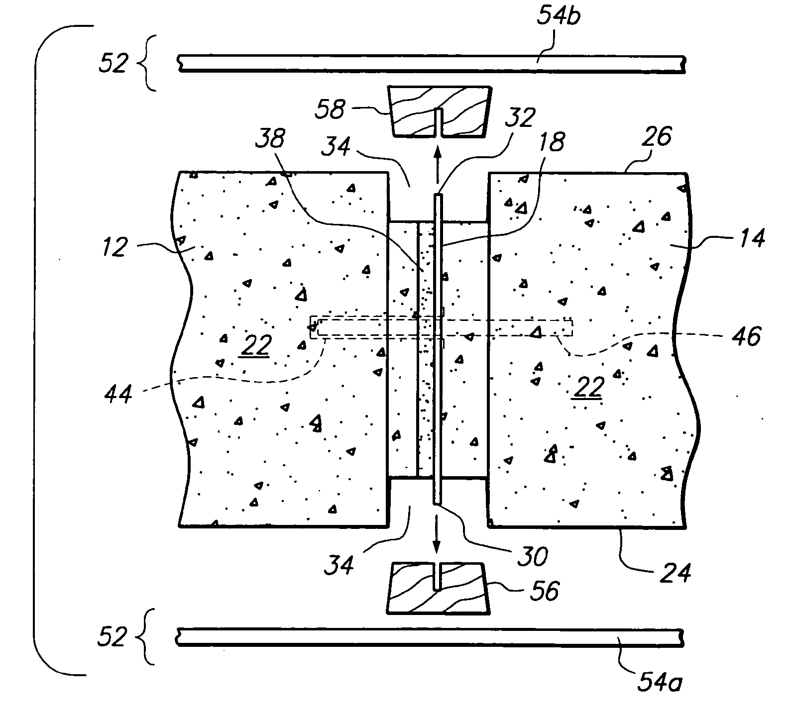
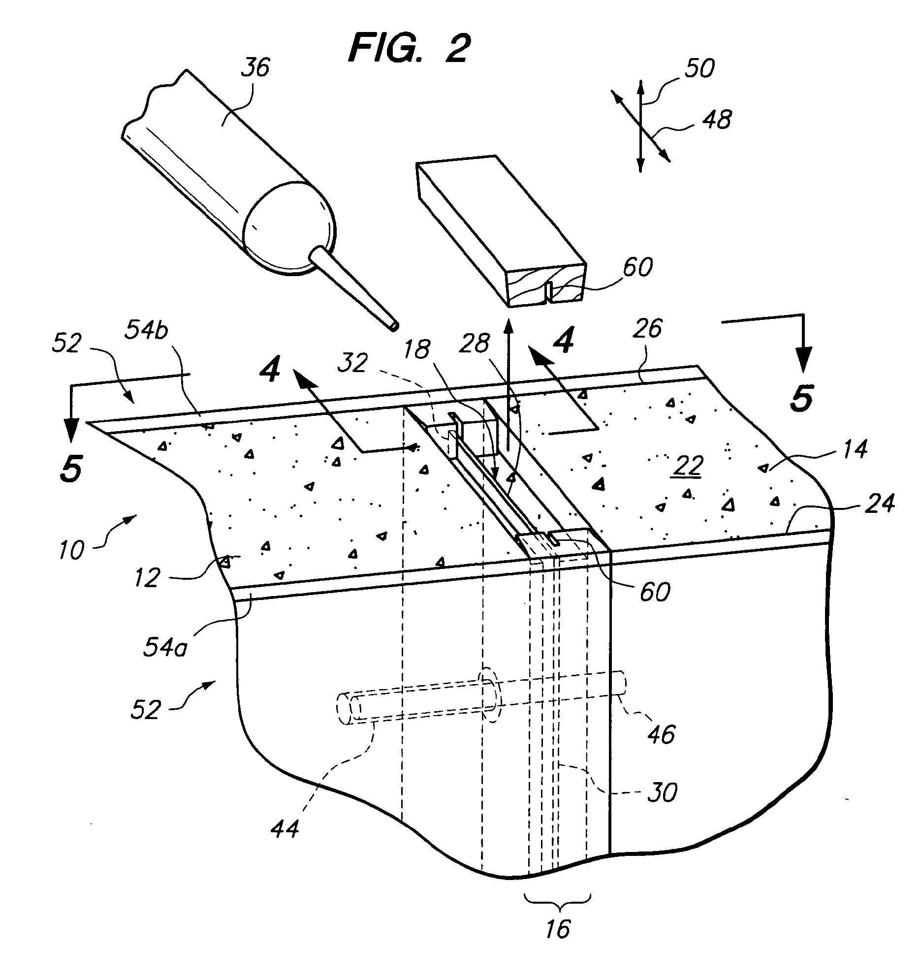
[0020]Referring now to FIG. 2, a concrete wall 10 is shown having a first concrete wall component 12 and a second concrete wall component 14 joined via an expansion joint system 16. The expansion joint system 16 allows the first concrete wall component 12 and the second concrete wall component 14 of the wall 10 to expand and contract due to temperature fluctuations and humidity fluctuations without stressing the first or second concrete wall component 12, 14 so as to cause cracks therein. Accordingly, the expansion joint system 16 controls cracks in the first and second concrete wall components 12, 14 to maintain the aesthetic appeal of the wall 10.

[0021]The expansion joint system 16 may comprise a rigid plate 18 disposed between the first and second concrete wall components 12, 14. The rigid plate 18 may be smaller than a cross-sectional area of the first and second concrete wall components 12, 14. In particular, each of the first and second concrete wall components 12, 14 may defi...


PUM


Abstract

An expansion joint system for a wall is provided herein wherein a first concrete wall component is substantially separated from a second concrete wall component via a rigid plate such that contraction of the first concrete wall component does not create significant stresses in the first or second concrete wall component so as to create cracks in the first or second concrete wall component. Moreover, a compressible material may be disposed between the rigid plate and / or the first and / or second concrete wall component such that expansion of the first concrete wall component compresses the compressible material instead of imposing significant stresses on the first or second concrete wall component so as to be likely to form cracks in the first or second concrete wall component.

Description

CROSS-REFERENCE TO RELATED APPLICATIONS[0001]Not ApplicableSTATEMENT RE: FEDERALLY SPONSORED RESEARCH / DEVELOPMENT[0002]Not ApplicableBACKGROUND[0003]The present invention relates to a concrete wall structure.[0004]One problem in building or constructing large concrete walls is cracks that form in the concrete wall due to the expansion or contraction of the concrete wall. The concrete wall expands and contracts due to changes in humidity and temperature. Although in small concrete walls, the amount of expansion and contraction of the concrete wall may be structurally negligible, in large concrete walls, the aggregate amount of expansion or contraction may be structurally significant to impose significant stresses on the concrete wall to crack the same.[0005]To mitigate against the likelihood of cracks in a large concrete wall, large concrete walls are typically constructed in smaller segments. By way of example and not limitation, a long concrete wall (see FIG. 1) may be formed via a...

Claims


Application Information

Patent Timeline
Patent Type & Authority Applications(United States)
IPC IPC(8): E04B1/68E04B1/61E04G21/00E04B2/84E04B1/16
CPCE04B1/6812E04B1/48E04B1/483
Inventor SHAW, LEE A.SHAW, RONALD D.
Owner SHAW & SONS
Learn More