Indexed positive displacement rotary motion device

a positive displacement, rotary motion technology, applied in the direction of rotary or oscillating piston engines, rotary piston engines, engine lubrication, etc., can solve the problems of inability to achieve spacing system, low viscosity gas has difficulty maintaining a gap seal between the two rotors, and rotor-to-rotor conta

Inactive Publication Date: 2010-03-25
EXPONENTIAL TECHNOLOGY
View PDF29 Cites 34 Cited by
  • Summary
  • Abstract
  • Description
  • Claims
  • Application Information

AI Technical Summary

Problems solved by technology

However, one issue with the rotary devices as shown in the prior art is that the two mating gear-like members generally must engage one another or have a fluid film therebetween to maintain separation thereof.
This type of device discloses a positive displacement device but, for example, if a low-viscosity fluid such as a gas is positioned within the bucket regions for a gas expander or a compressor, this low viscosity gas has difficulty maintaining a gap seal between the two rotors, and rotor-to-rotor contact can occur.
Through various failures of rotary motion positive displacement devices, it became apparent that a need for positioning the rotors spaced apart from one another is require...

Method used


Image

  • Indexed positive displacement rotary motion device
  • Indexed positive displacement rotary motion device
  • Indexed positive displacement rotary motion device

Examples


Embodiment Construction

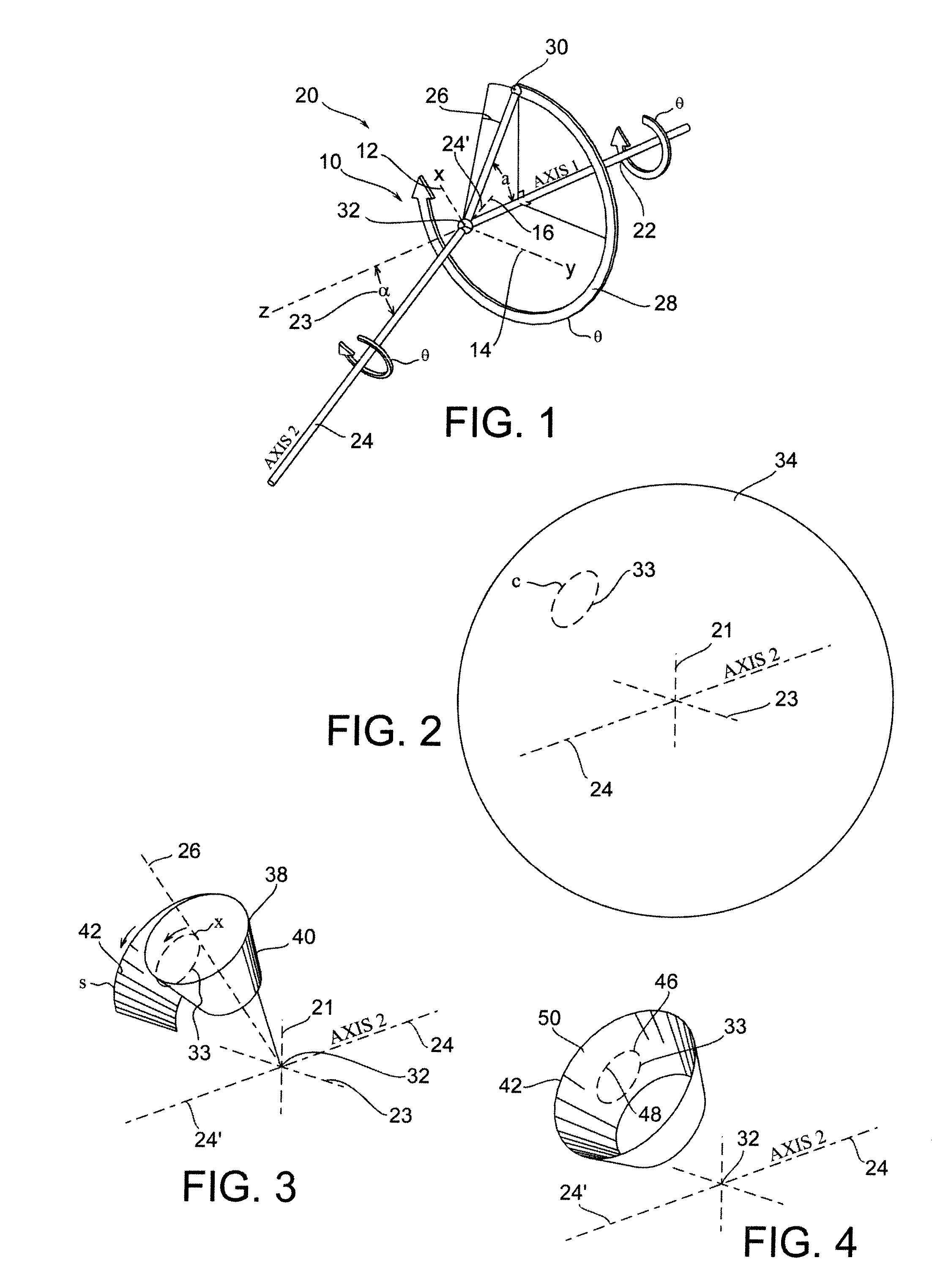
[0133]As shown in FIG. 1, there is a first axis system 20, which comprises a first axis 22, a second axis 24, and a reference axis 26. In general, for purposes of discussion, the reference axis 26 is set at a prescribed angle “a” about the first axis 22 and as axes 22 and 24 rotate by an equal amount, the arc path 28 is formed and a prescribed amount of rotation about axis 1 is defined by the value theta (θ). It should be noted that there is a correlating amount of rotation of the value theta in a first form wherein an equal number of lobes are formed. However, the amount of rotation about axes 1 and 2 can alter in further embodiments described herein.

[0134]As shown in FIG. 1, a reference axis system 10 is defined wherein the axis 12 indicates an X direction and the axis 14 indicates the Y direction. Further, the axis extension indicated at 24′, otherwise referred to as 16, is the Z direction, which is co-linear with the axis 24 which is the center of rotation of the rotor correspon...


PUM


Abstract

An indexing system for a rotor assembly where the indexing system can regulate the rotational location of drive rotors that are configured to rotate about a shaft in one form.

Description

RELATED APPLICATIONS[0001]This application claims priority benefit of U.S. Ser. Nos. 61 / 097,744, filed Sep. 17, 2008, 61 / 110,770, filed Nov. 3, 2008, 61 / 142,035, filed Dec. 31, 2008 and 61 / 181,236 filed May 26, 2009.BACKGROUND OF THE DISCLOSURE[0002]Described herein is a method for creating surfaces to be utilized on rotating devices having rotational axes offset from being co-linear, and in a preferred form intersecting at a center location.[0003]In general, the prior art related to rotary composite displacement devices has disclosed various types of mechanisms, some of which include mechanisms operating in a cyclic reciprocating-type pattern, such as a piston-and-cylinder type design which is utilized in most automotive engines. Other types of positive displacement devices, such as the Wankel engine, may have a reciprocating member which rotates with an elongated cylinder shaped somewhat like a peanut. The Wankel engine is of course a commercially successful engine utilized in var...

Claims


Application Information

Patent Timeline
IPC IPC(8): F01C3/08
CPCF01C1/107F01C3/085F01C21/08F05D2250/232F02C5/00F04C2250/201F02C3/165F01C1/10F01C1/20F01C21/10F02B53/04F02B53/10F02B53/12F04C3/085F04C18/48
Inventor JUAN, ALEJANDROPATTERSON, CURTISGOTTFRIED, KRISJANFARSHCHIAN, SOHEIL
Owner EXPONENTIAL TECHNOLOGY
Why Eureka
Try Eureka