RFID tag based discrete contact position indication

a discrete contact position and tag technology, applied in the field of switches, can solve the problems of increasing the number of state indicators, increasing the cost of hardware requirements, and increasing the number of wiring coupled to the state indicators

Active Publication Date: 2010-04-01
ROCKWELL AUTOMATION TECH
View PDF5 Cites 73 Cited by
  • Summary
  • Abstract
  • Description
  • Claims
  • Application Information

AI Technical Summary

Problems solved by technology

As power control systems and the logic required to control these systems become more complex, the number of state indicators increases, and the wiring coupled to the state indicators also increases.
The increased wiring, in turn, leads to increased costs due to hardware requirements, connection labor and wiring maintenance.
An increase in the number of wires increases maintenance problems due to wiring failure and inconvenient tethering of door-mounted devices with internal devices.
Additionally, because there is a limit to how many wires can be placed under the common screw-terminal connectors, hardware is often added to control devices in the form of additional contacts driven by a mechanical or electromechanical shaft called an operator.
Furthermore, each electrical connection

Method used


Image

  • RFID tag based discrete contact position indication
  • RFID tag based discrete contact position indication
  • RFID tag based discrete contact position indication

Examples


Embodiment Construction

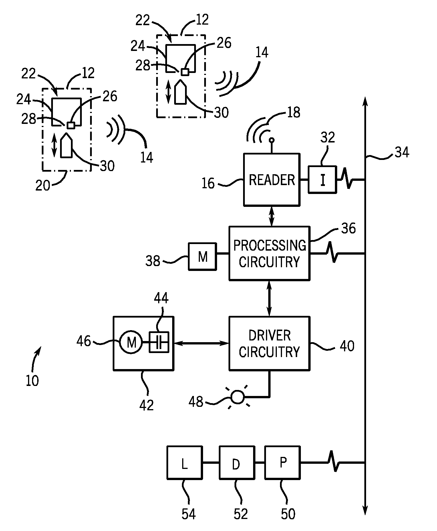
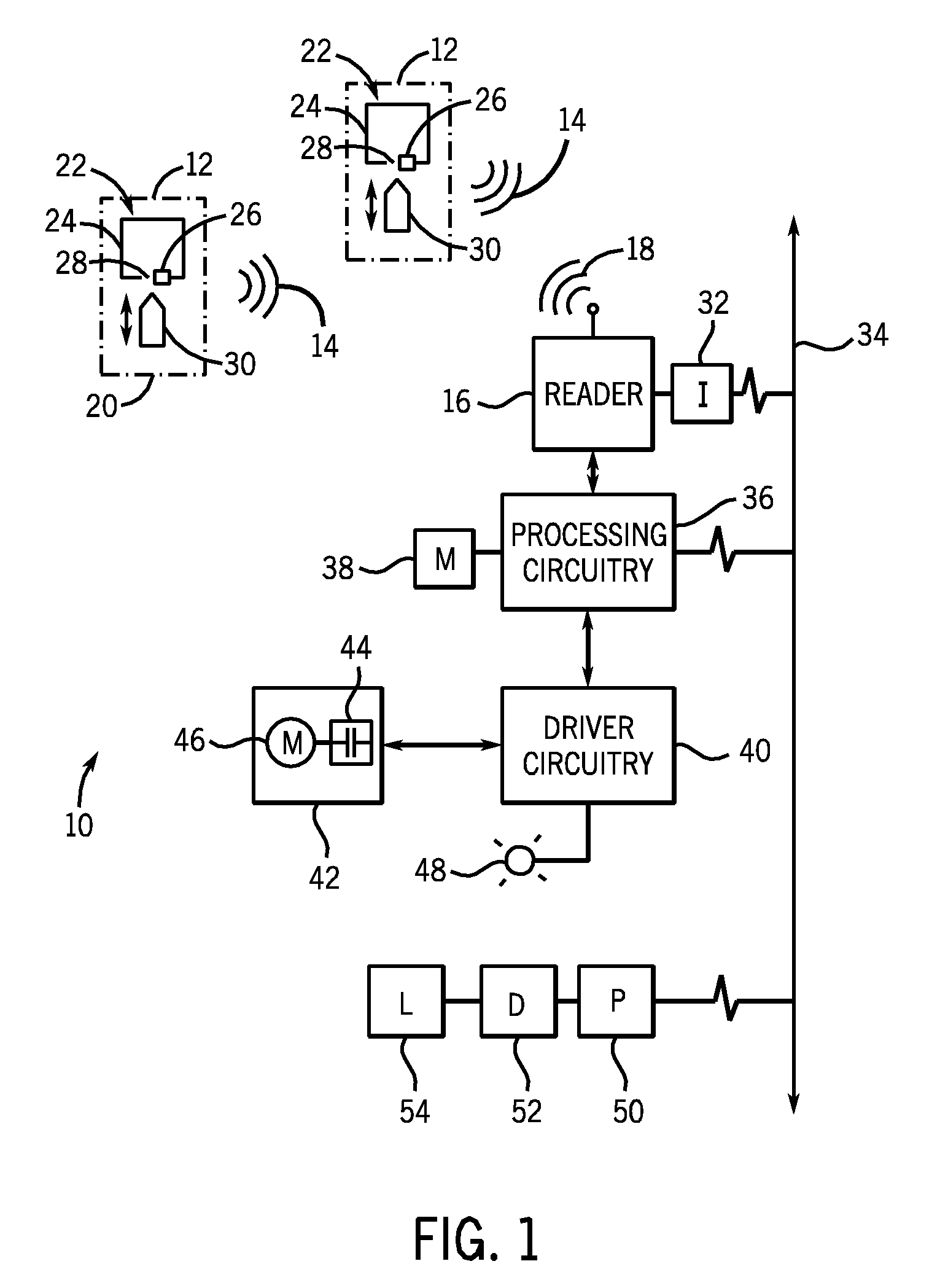
[0015]Turning now to the drawings, and referring first to FIG. 1, an exemplary control system is illustrated and designated generally by reference numeral 10. The control system 10 may include a plurality of RFID state selectors or indicators 12 (referred to herein simply as state indictors). Although FIG. 1 depicts two RFID state indicators, it should be noted that the present invention is not limited to any particular number of RFID state indicators. In embodiments of the present invention, the RFID state indicators 12 are input devices used to facilitate user control of some operational aspect of the control system 10, as will be explained below. In other embodiments, the RFID state indicators 12 are coupled to components within the control system 10 such as to provide an indication of the operational state of the control system 10.

[0016]Also included in the control system 10 is a reader 16. The reader 16 may be any device known to those of ordinary skill in the art for communica...


PUM


Abstract

An RF based state indicator for indicating the state of a control device is provided. The RF-based state indicator indicates the position of a control mechanism by using the position of the control mechanism to enable or disable an RF tag. An RF reader acquires RF transmitted data from enabled RF tags and uses the data to indicate or control an operation aspect of a device.

Description

BACKGROUND[0001]The invention relates generally to the field of switches and similar devices used to control application of power to electrical loads. More particularly, the invention relates to the use of radio frequency identification (RFID) tags to indicate the state of an input device, such as a pushbutton, an electrical contact, a relay or contactor, and so forth.[0002]In the field of electronics, a wide range of control devices is used for controlling the delivery of power to a load. Such control devices may include various switches, relays, contactors and disconnects to control load power, circuit breakers to protect electrical circuits from overload, and pushbuttons and selector switches to facilitate user control of power circuit operation. Additionally, a variety of electrical devices are known and currently available for indicating the state of a control device. For example, an auxiliary contact is often coupled to a contactor so that the auxiliary contact produces an aux...

Claims


Application Information

Patent Timeline
IPC IPC(8): G08B21/00H04Q5/22G08B13/14
CPCH01H9/168H01Q1/2216H01Q1/2208
Inventor BRANDT, DAVID DALEWIELEBSKI, WAYNE H.
Owner ROCKWELL AUTOMATION TECH
Why Eureka
Try Eureka