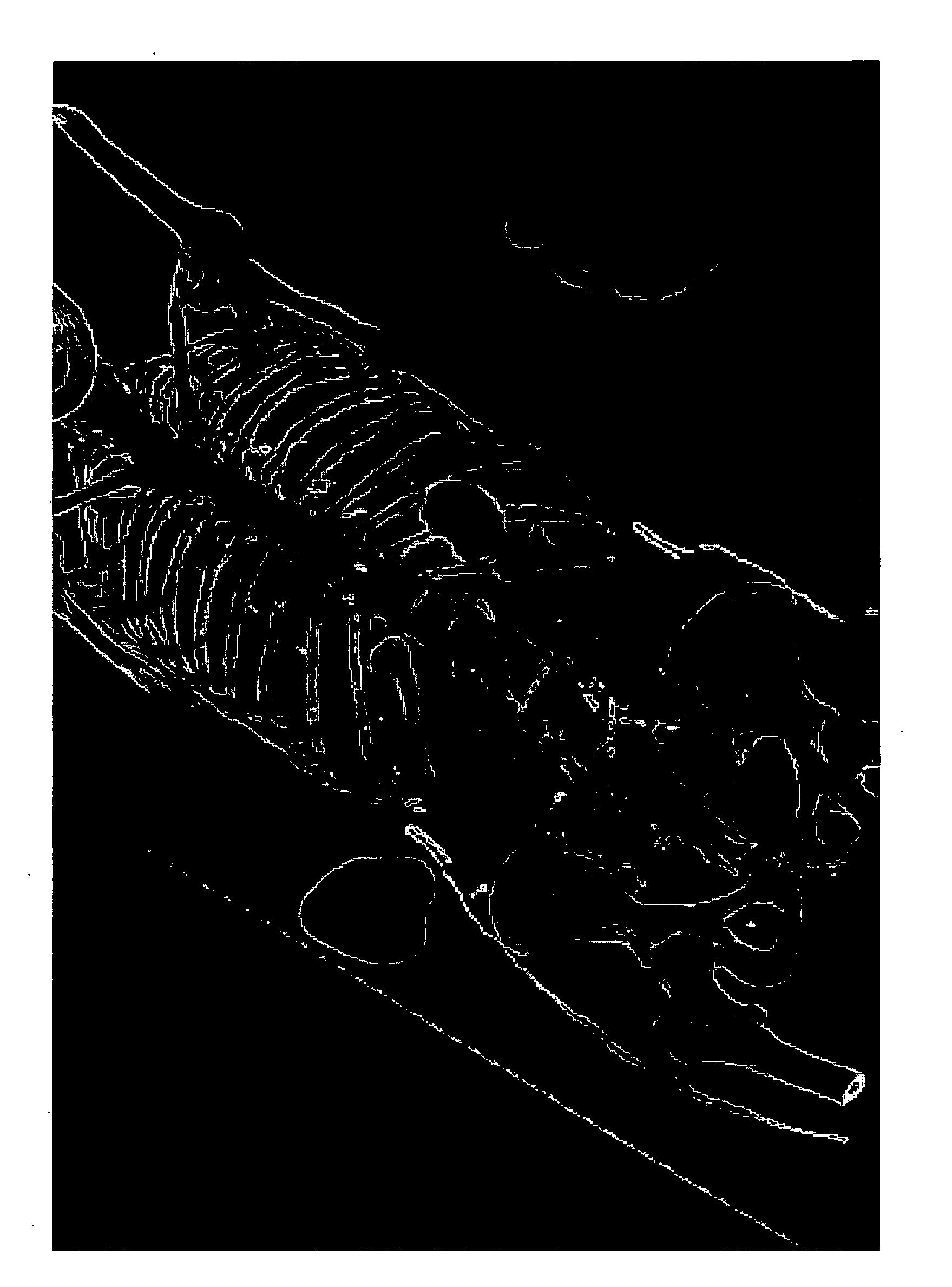
Accelerated texture-based fusion renderer

a texture-based fusion and renderer technology, applied in the field of imaging, can solve the problems of insufficient speed of resample-based fusion render, significant increase in processing time (both initially and for each rendering), and inability to meet such requirements quickly enough

Active Publication Date: 2010-04-01
SIEMENS HEALTHCARE GMBH +1
View PDF8 Cites 15 Cited by
  • Summary
  • Abstract
  • Description
  • Claims
  • Application Information

AI Technical Summary

Problems solved by technology

Therefore, re-sampling can significantly increase the processing time (both initially and for each rendering) as well as the amount of memory required.
The resample-based fusion render cannot response quickly enough for such requirements.

Method used


Image

  • Accelerated texture-based fusion renderer
  • Accelerated texture-based fusion renderer
  • Accelerated texture-based fusion renderer

Examples


Embodiment Construction

[0016]Illustrative embodiments of the invention are described below. In the interest of clarity, not all features of an actual implementation are described in this specification. It will of course be appreciated that in the development of any such actual embodiment, numerous implementation-specific decisions must be made to achieve the developers' specific goals, such as compliance with system-related and business-related constraints, which will vary from one implementation to another. Moreover, it will be appreciated that such a development effort might be complex and time-consuming, but would nevertheless be a routine undertaking for those of ordinary skill in the art having the benefit of this disclosure.

[0017]While the invention is susceptible to various modifications and alternative forms, specific embodiments thereof have been shown by way of example in the drawings and are herein described in detail. It should be understood, however, that the description herein of specific em...


PUM


Abstract

An exemplary method of combining two images to form a fused image is provided. A hierarchical structure for each of a plurality of volumes is built. All blocks in each of the hierarchical structures that intersect a slicing plane are found. Each of the plurality of volumes is divided into stacks of parallel slices, and the parallel slices are sorted by visibility order. A next slice in the sorted parallel slices is chosen. The next slice belongs to a current volume. Rendering parameters are changed if the current volume is different from a previous volume associated with the chosen slice in a previous iteration of the step of choosing the slice. Based on the rendering parameters, the next slice is rendered by intersecting the slicing plane with the blocks corresponding to the current volume. The steps of choosing the slice, changing the rendering parameters, and rendering the slice are repeated until all of the sorted parallel slices are rendered.

Description

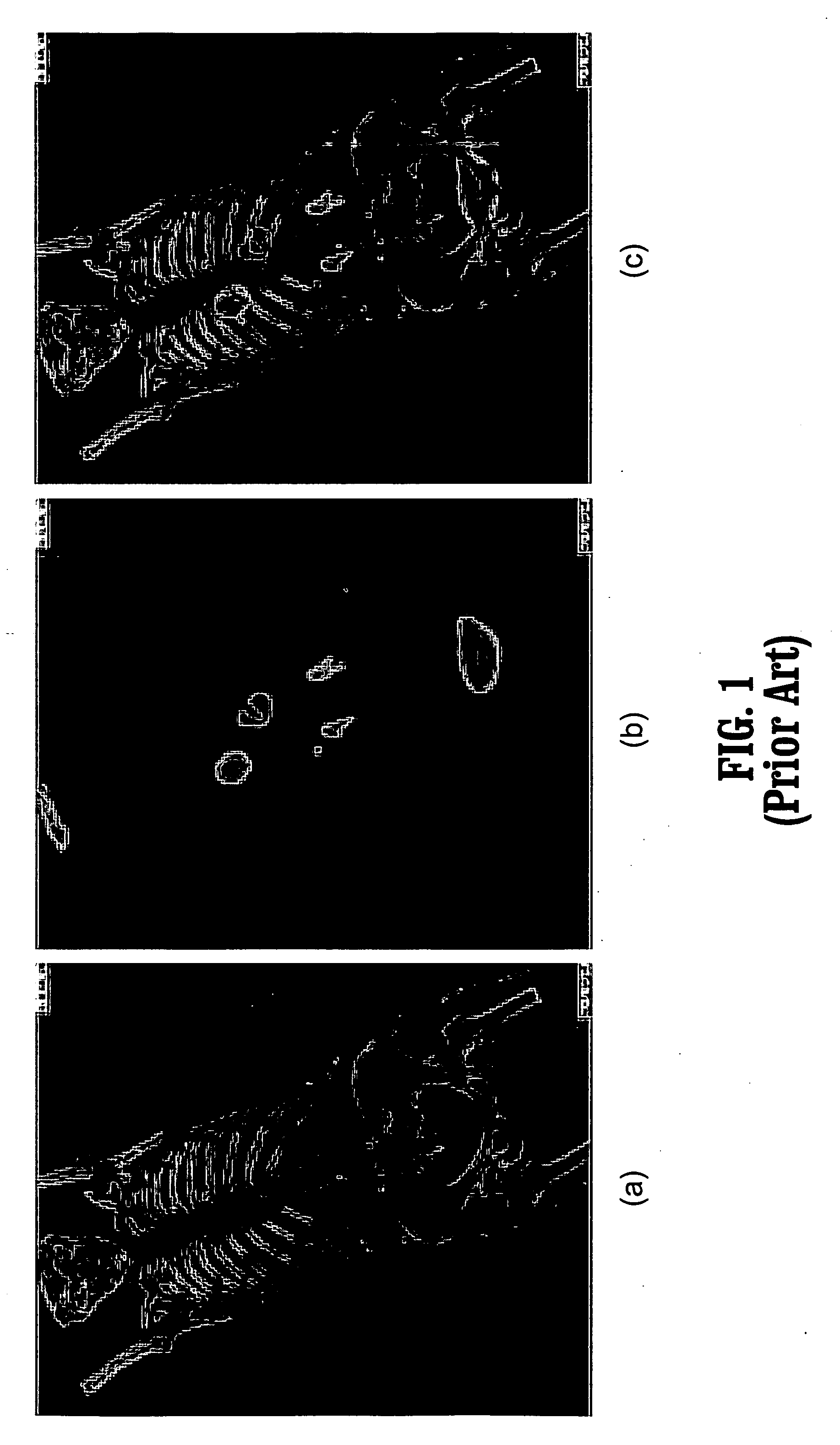
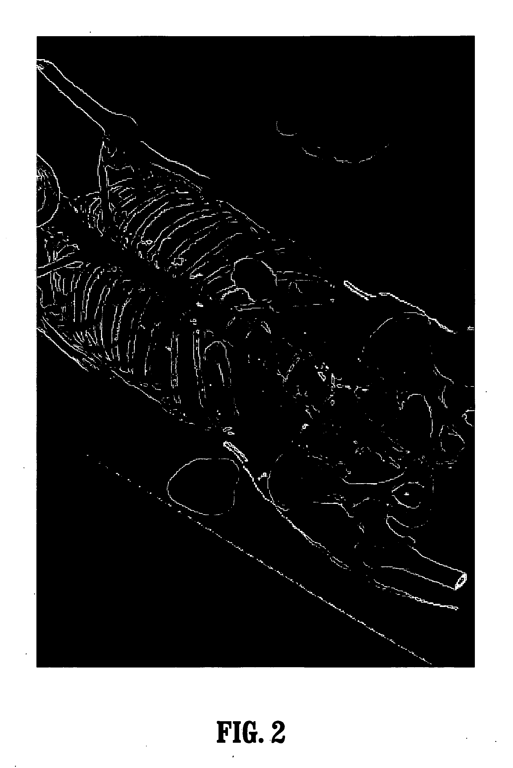
CROSS-REFERENCE TO RELATED APPLICATIONS[0001]This application claims priority to U.S. Provisional Application No. 60,647,713, which was filed on Jan. 27, 2005, and which is fully incorporated herein by reference.BACKGROUND OF THE INVENTION[0002]1. Field of the Invention[0003]The present invention relates generally to the field of imaging, and, more particularly, to an accelerated texture-based fusion renderer.[0004]2. Description of the Related Art[0005]Modern medical technology provides different modalities for acquiring 3D data, such as computed tomography (“CT”), magnetic resonance imaging (“MRI”), positron emission tomography (“PET”), and ultrasound. The information obtained from different modalities is usually complementary; for example, CT provides structural information while PET provides functional information. Thus, it is generally desirable to fuse multiple volumetric datasets.[0006]FIG. 1 presents a sample fused image where functional data from PET is correlated with stru...

Claims


Application Information

Patent Timeline
Patent Type & Authority Applications(United States)
IPC IPC(8): G06K9/00G06T17/00G06T15/40
CPCG06T19/00G06T15/08
Inventor LI, WEI
Owner SIEMENS HEALTHCARE GMBH
Why Eureka
Try Eureka