System and method for constructing a 3D scene model from an image

image technology, applied in the field of computer vision, can solve the problems of not having an entirely satisfactory method for reliably constructing a 3d scene model, many difficult problems in doing,

Active Publication Date: 2010-04-08
STRIDER LABS
View PDF2 Cites 38 Cited by
  • Summary
  • Abstract
  • Description
  • Claims
  • Application Information

AI Technical Summary

Benefits of technology

[0009]The present invention also provides a method for computing alternative 3D scene models, comprising 3D objects and representing a scene, based upon a set of possible prior 3D scene models. The method comprises the steps of acquiring an image of the scene; initializing the set of alternative 3D scene models to the set of possible prior 3D scene models; determining differences between one or more of the alternative 3D scene models and the image; and modifying one or more of the alternative 3D scene models by addin

Problems solved by technology

There are many difficult problems in doing this.
Previously, there has been no entirely satisfactory method for reliably constructing a 3D scene model, in spite of considerab

Method used


Image

  • System and method for constructing a 3D scene model from an image
  • System and method for constructing a 3D scene model from an image
  • System and method for constructing a 3D scene model from an image

Examples


examples

[0043]Some examples will illustrate the utility of the present invention, showing the results computed by typical embodiments.

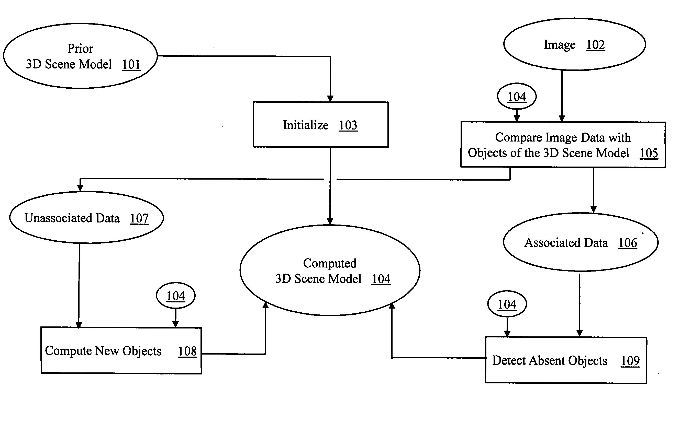
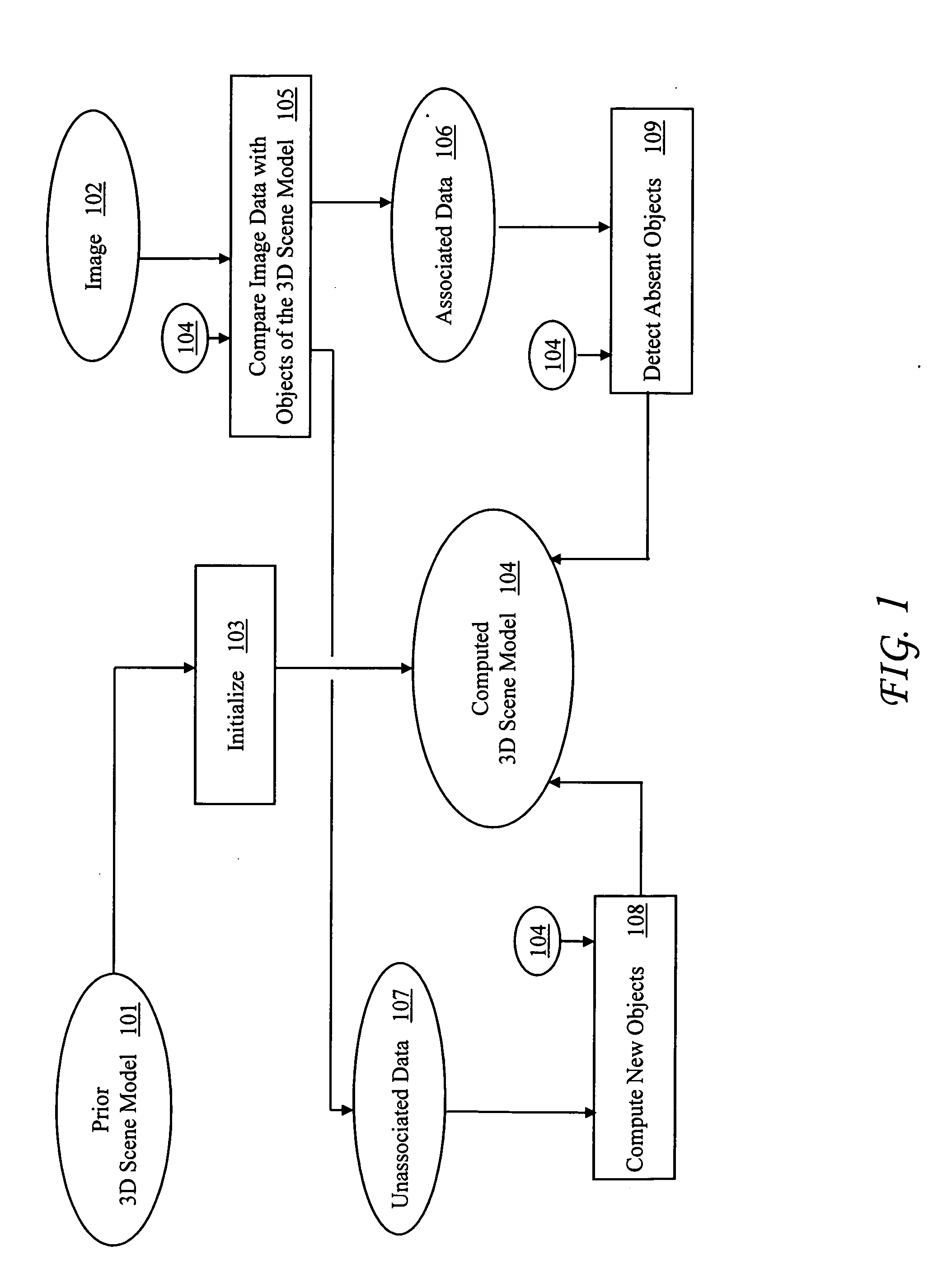
[0044]Suppose there is a scene with an object pl. Subsequently, an object pf is placed in front of pl, occluding it from direct observation from the imaging device. Then an image of the scene is acquired. Persistence suggests that pl has remained where it was, even though it appears nowhere in the image, and this persistence is expressed in the dynamic model. The present invention computes a new 3D scene model in which the occluded object remains present and designated as Unverifiable, meaning that the image data neither confirms nor contradicts its presence. Using a prior 3D scene model allows the method to retain hidden state, possibly over a long duration in which the object cannot be observed.

[0045]Suppose there is a scene with an upright cylinder pc. Subsequently, a second cylinder pd of identical radius and visual appearance is placed on it. An image is...

first embodiment

The first embodiment uses τ=3 σ, where σ is the standard deviation of equation (3). The quality of the data association is the distance of a data point to the object to which it is associated.

[0159]The signed distance function E is defined for three shapes: spheres, cylinders, and cuboids. Let t=(x,y,z)T. For a sphere with radius r and center c=(cx; cy; cz)T, the signed distance function is

Es(c, r; t)=sqrt((x−cx)2+(y−cy)2+(z−cz)2)−r   (5)

For a cylinder with height h, radius r, center c=(cx; cy; cz)T and orientation described by rotation R, the signed distance function is

EC(c, R, h, r; t)=max(sqrt(x′2+y′2)−r, |z′|−h / 2)   (6)

where (x′,y′,z′)T=RT(t−c).

For a cuboid with center c, orientation described by rotation R, and dimensions d=(dx, dy, dz)T the signed distance function is

EB(c, R, d; t)=max (|x′|−dx / 2, |y′|−dy / 2, |z′|−dz / 2)   (7)

where (x′,y′,z′)T=RT(t−c).

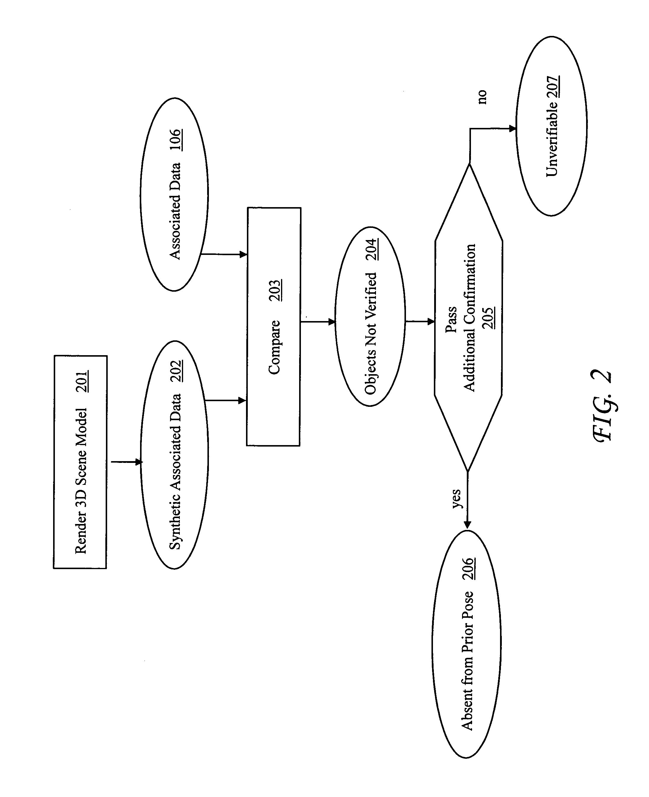
Object Presence Test

[0160]Referring to step 203 of FIG. 2, to test an object instance p for object presence, the set of locations...


PUM


Abstract

A system and method for constructing a 3D scene model comprising 3D objects and representing a scene, based upon a prior 3D scene model. The method comprises the steps of acquiring an image of the scene; initializing the computed 3D scene model to the prior 3D scene model; and modifying the computed 3D scene model to be consistent with the image. The step of modifying the computed 3D scene models consists of the sub-steps of comparing data of the image with objects of the 3D scene model, resulting in associated data and unassociated data; using the unassociated data to compute new objects that are not in the 3D scene model and adding the new objects to the 3D scene model; and using the associated data to detect objects in the prior 3D scene model that are absent and removing the absent objects from the 3D scene model. The present invention may also be used to construct multiple alternative 3D scene models.

Description

FIELD OF THE INVENTION [0001]The present invention relates generally to computer vision and, more particularly, to constructing a 3D scene model from an image of a scene.BACKGROUND OF THE INVENTION [0002]Various techniques can be used to obtain an image of a scene. The image may be intensity information in one or more spectral bands, range information, or a combination of the two. From such an image, it is useful to compute the full 3D model of the scene. One need for this is in robotic applications where the full 3D scene model is required for path planning, grasping, and other manipulation. In such applications, it is also useful to know which parts of the scene correspond to separate objects that can be moved independently of other objects. Other applications have similar requirements for obtaining a full 3D scene model that includes segmentation into separate parts.[0003]Computing the full 3D scene model from an image of a scene, including segmentation into parts, is referred to...

Claims


Application Information

Patent Timeline
IPC IPC(8): G06T17/00
CPCG06T2219/2021G06T19/20
Inventor WEGBREIT, ELIOT LEONARDHAGER, GREGORY D.
Owner STRIDER LABS
Why Eureka
Try Eureka