Systems for thermal patterning

a technology of thermal patterning and thermal patterning, applied in the direction of power drive mechanism, printing, instruments, etc., can solve the problems of difficult control of quality, complicated and expensive lithography fabrication methods, and low production throughpu

Active Publication Date: 2010-04-08
IND TECH RES INST
View PDF3 Cites 1 Cited by
  • Summary
  • Abstract
  • Description
  • Claims
  • Application Information

AI Technical Summary

Problems solved by technology

However, fabrication method using lithography is complicated and expensive.
However, production throughput is very slow.
Additionally, quality is not easy to control due to unstable laser sources.
Inkjet droplets, however, are not easily applied on some materials.
Additionally, pattern quality is unstable due to volatile inkjet droplets and crooked ink trajectory.

Method used


Image

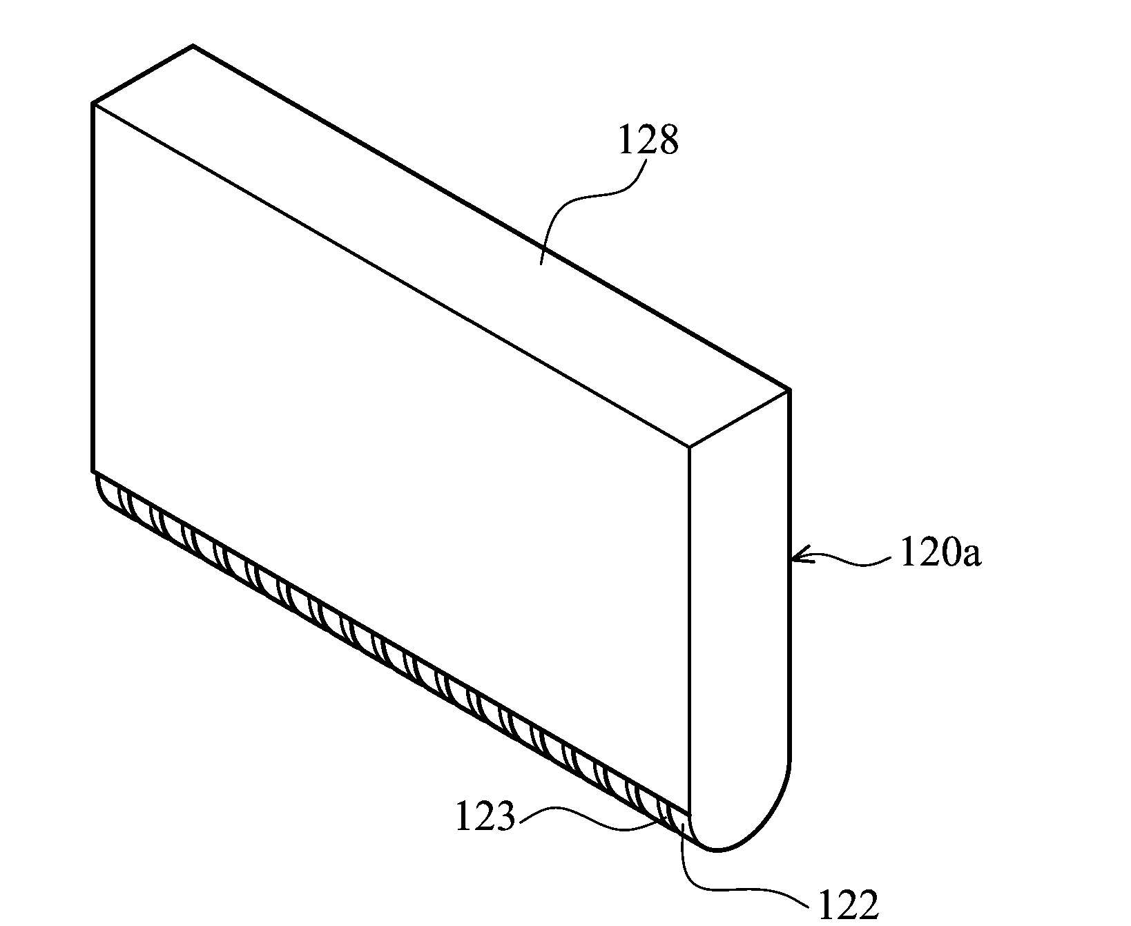
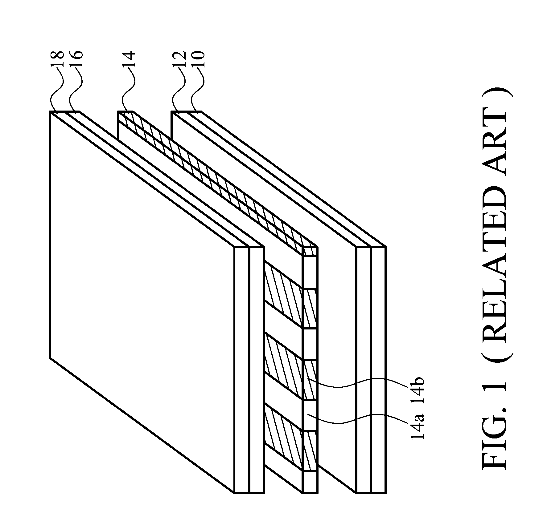
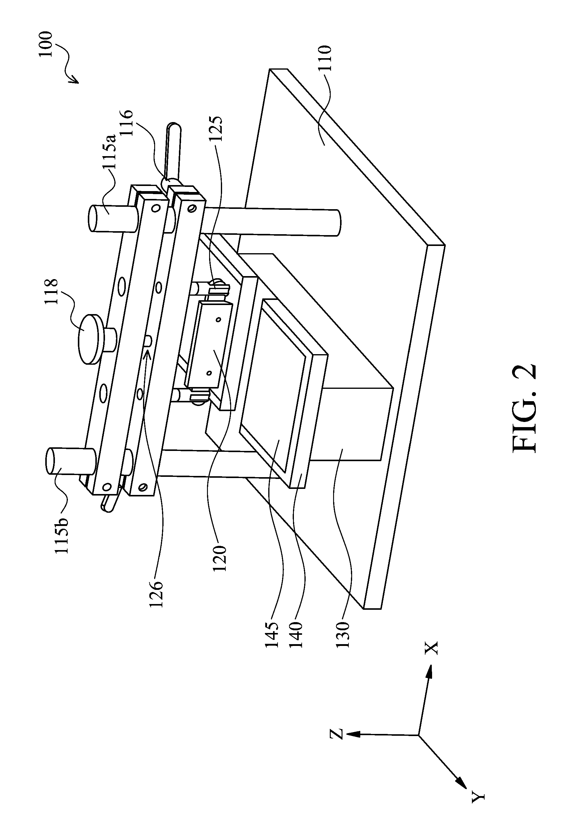
  • Systems for thermal patterning
  • Systems for thermal patterning
  • Systems for thermal patterning

Examples


Embodiment Construction

[0021]It is to be understood that the following disclosure provides many different embodiments, or examples, for implementing different features of various embodiments. Specific examples of components and arrangements are described below to simplify the present disclosure. These are merely examples and are not intended to be limiting. In addition, the present disclosure may repeat reference numerals and / or letters in the various examples. This repetition is for the purpose of simplicity and clarity and does not in itself indicate a relationship between the various embodiments and / or configurations discussed. Moreover, the formation method for a first feature over or on a second feature in the description that follows may include embodiments in which the first and second features are formed in direct contact or not in direct contact.

[0022]Embodiments of the invention provide thermal patterning techniques applied to large scale flexible substrates and large scale display regimes. The ...


PUM


Abstract

Systems for thermal patterning are presented. The system includes a thermal print head module. The thermal print head module includes at least one point heater. An elastic adjustable device is used for adjusting the flatness of the thermal print head module. A rotation adjustable device is used for controlling the thermal print head module to rotate with a predetermined angle.

Description

CROSS REFERENCE TO RELATED APPLICATIONS[0001]This application is based upon and claims the benefit of priority from a prior Taiwanese Patent Application No. 097138183, filed on Oct. 3, 2008, the entire contents of which are incorporated herein by reference.BACKGROUND OF THE INVENTION[0002]1. Field of the Invention[0003]The invention relates to a system for thermal patterning.[0004]2. Description of the Related Art[0005]Display panels have been developed towards large scale and flexible regimes. In order to achieve fast and precise production, conventional fabrication methods for patterned structures include lithography, laser processing, inkjet printing, and thermal print-heat patterning.[0006]Conventional lithography is beneficial due to the fact that its well-developed. However, fabrication method using lithography is complicated and expensive. Further, CO2 laser processing is advantageous due to the fact that it can be practically used. A pattern is created by several laser-scann...

Claims


Application Information

Patent Timeline
Patent Type & Authority Applications(United States)
IPC IPC(8): B41J2/32
CPCB41J2/32
Inventor CHEN, YING-CHITSAI, CHAO-HSU
Owner IND TECH RES INST
Why Eureka
Try Eureka