Shear wave generation method, shear wave imaging method and thermal mapping or treating method utilizing such a generation method and installation for generating at least one shear wave

a generation method and generation method technology, applied in the field of shear wave generation method, shear wave imaging method and thermal mapping or treating method, can solve the problems of obtaining a non-linear behaviour of the medium, affecting the detection effect, so as to achieve the effect of convenient detection

Active Publication Date: 2017-01-12
INST NAT DE LA SANTE & DE LA RECHERCHE MEDICALE (INSERM) +2
View PDF3 Cites 1 Cited by
  • Summary
  • Abstract
  • Description
  • Claims
  • Application Information

AI Technical Summary

Benefits of technology

[0023]Thanks to the invention, the modified shear waves originating from the first and second sources combine with each other and can be optimized in order to focus at a given point of the target region, independently of the actual geometry and of the linear behaviour of the soft solid. In particular, this method can be used with a damping medium which is more representative of the actual soft solids used in practical applications than a agar-gelatin phantom.

Problems solved by technology

Agar-gelatin can be used from a theoretical point of view, but such a material is not representative of soft solids that could be used for practical and industrial applications.
This damping feature makes this known method relatively inaccurate.
In some cases, it might be necessary to obtain a non-linear behaviour of the medium, which cannot be obtained with the known methods because the induced stress level is not high enough for this.
Actually, because of their intrinsic technology, none of the commercial elastography methods is able to deliver a shear wave amplitu

Method used


Image

  • Shear wave generation method, shear wave imaging method and thermal mapping or treating method utilizing such a generation method and installation for generating at least one shear wave
  • Shear wave generation method, shear wave imaging method and thermal mapping or treating method utilizing such a generation method and installation for generating at least one shear wave
  • Shear wave generation method, shear wave imaging method and thermal mapping or treating method utilizing such a generation method and installation for generating at least one shear wave

Examples


Embodiment Construction

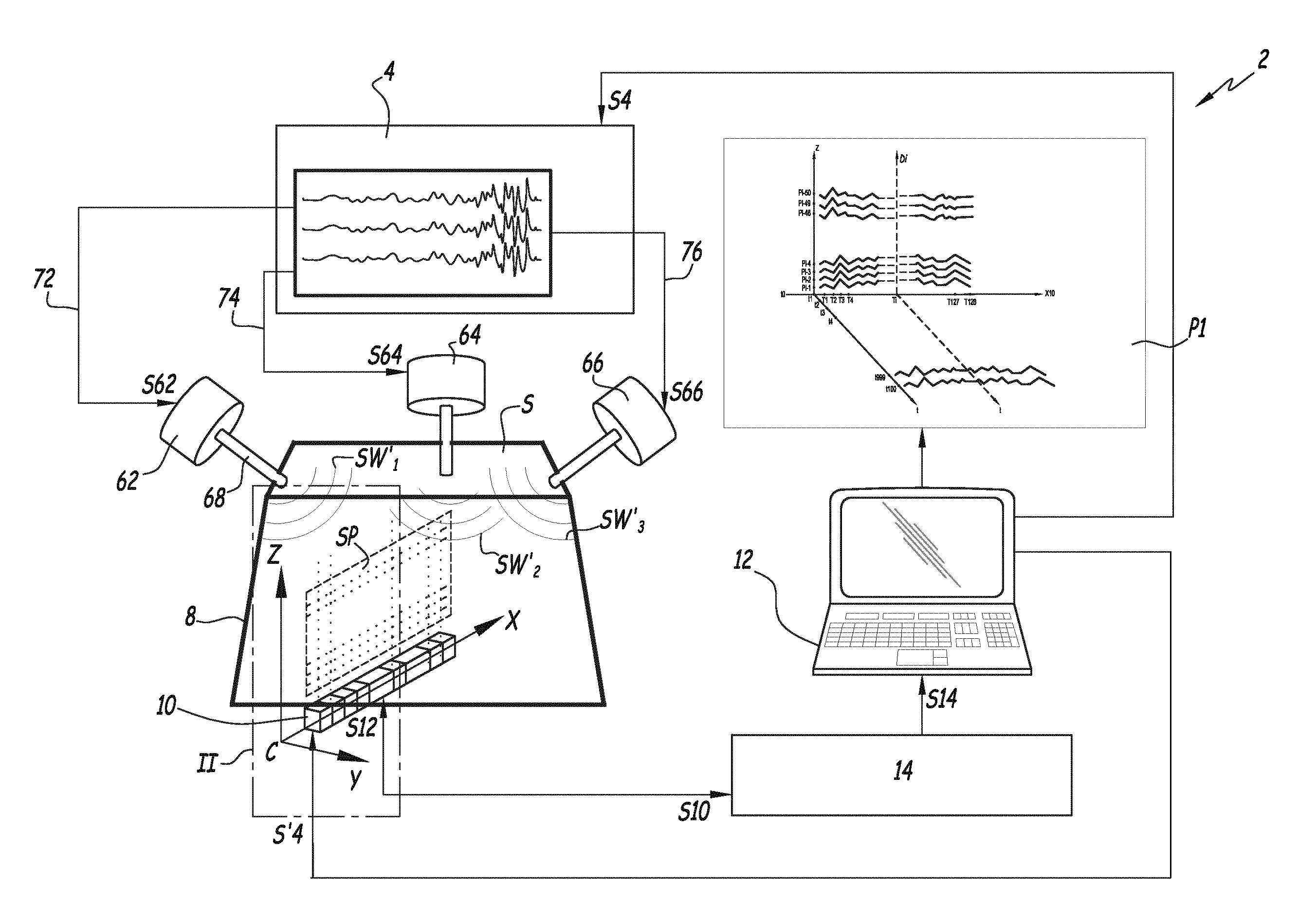
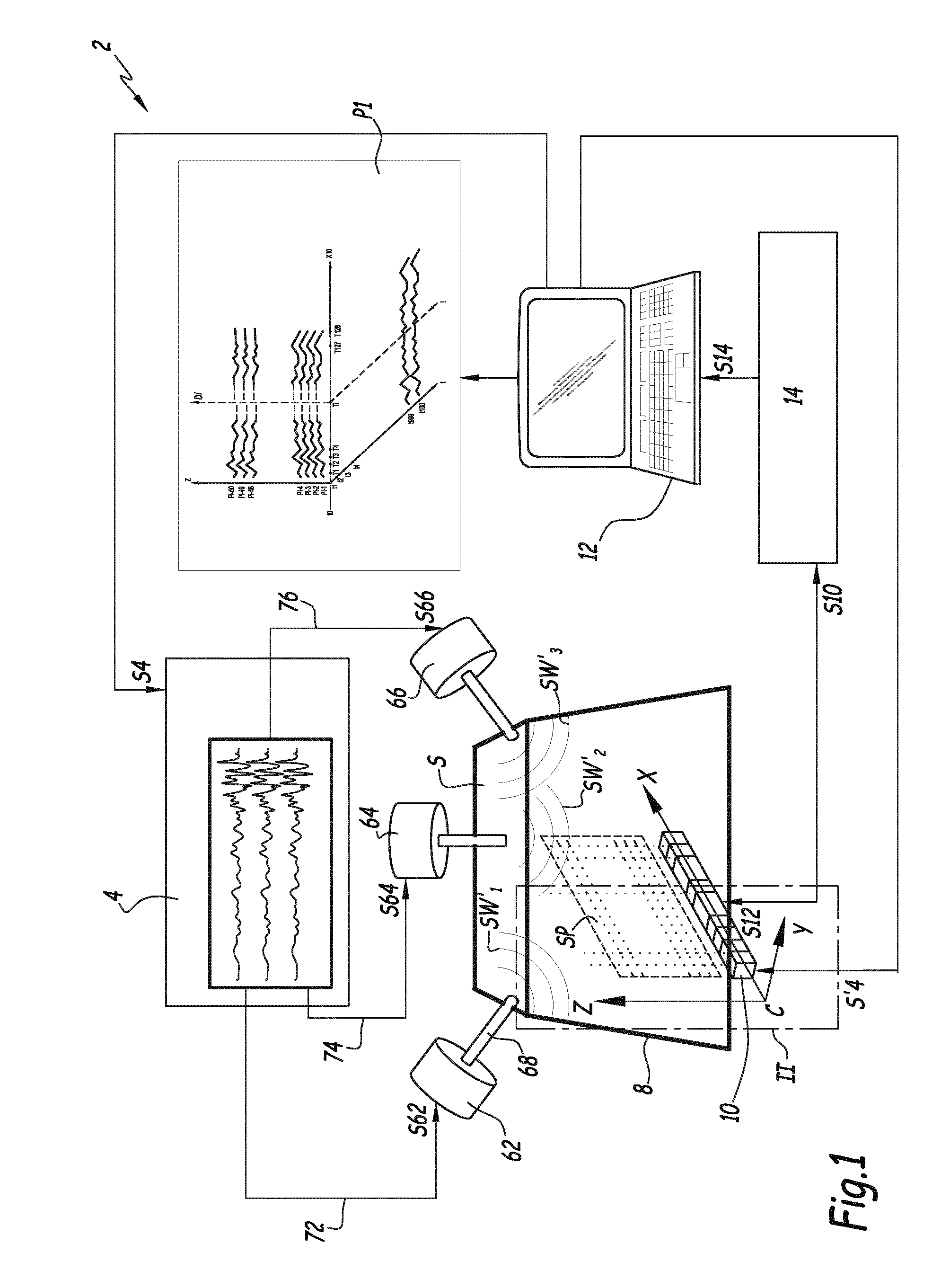
[0058]The installation 2 represented on FIGS. 1 and 2 includes an alternative current generator 4 which is connected to three shear wave sources 62, 64 and 66 by respective connection lines 72, 74 and 76 through which a drive signal S62, S64 and S66 travels. Each shear wave source is made of a piston vibrator and includes a reciprocating rod 68 connected to a non represented piston included in a housing of the shear wave source.

[0059]Installation 2 also includes a box 8 where a soft solid S is housed. Box 8 is optional and can be omitted if soft solid S stands on its own. Soft solid S can be a portion of an animal body, such as a muscle or a brain, or any other soft solid mentioned here-above.

[0060]Shear wave sources 62, 64 and 68 are fixedly mounted on box 8, with their respective rods 68 in contact with one surface of soft solid S. The location of sources 62, 64 and 66 is kept for all steps of the method of the invention.

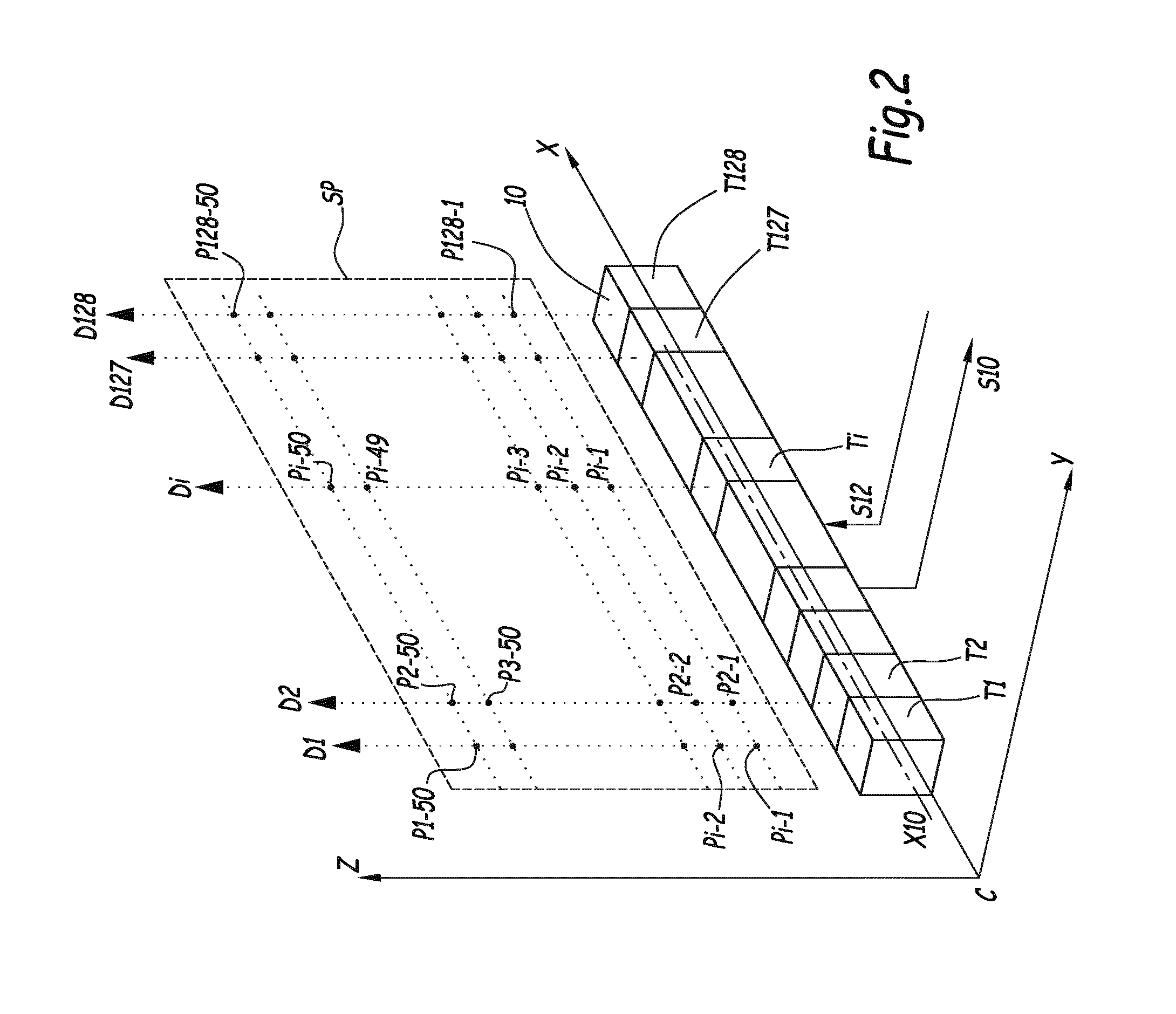
[0061]An array 10 of one hundred and twenty eight ultrasonic...


PUM


Abstract

Method for generating a shear wave in a target region of a soft solid, includes the following steps: a) generating at least two shear waves with a first and a second source of shear waves in the target region; b) detecting a propagation pattern of the shear wave in the target region with a detector unit including a row of ultrasonic transducers aligned on a first direction perpendicular to a detection direction of each or a single ultrasonic transducer movable along a first direction perpendicular to its detection direction; c) proceeding to a time reversal of the detected propagation pattern; and d) submitting the target region to an inverted excitation set of forces based on the temporally inverted propagation pattern. During step b), a first propagation pattern is detected when only the first source is active and a second propagation pattern is detected when only the second source is active.

Description

TECHNICAL FIELD OF THE INVENTION[0001]This invention relates to a method for generating at least one shear wave in a target region of a soft solid. This invention also relates to a shear wave imaging method and to a thermal mapping method for collecting information on a target region of a soft solid. This invention also concerns a method for thermally treating a target region of a soft solid. This invention also relates to an installation for generating at least one shear wave in a target region of a soft solid, this installation being useful to implement the above-mentioned methods.[0002]In the meaning of the present invention, a soft solid is an organic tissue which can have an animal or vegetal origin. For instance, such a soft solid can be an organ of a human body, of an animal body or of a vegetable. A soft solid can also be an aliment, e.g. cheese, or a non metallic part of prosthesis, made of a natural or synthetic material.BACKGROUND OF THE INVENTION[0003]Shear wave elastogr...

Claims


Application Information

Patent Timeline
IPC IPC(8): A61B8/08A61B5/00G01S7/52A61B5/01G01S15/89A61B8/00A61B5/055
CPCA61B8/485A61B8/4477A61B8/4466A61B8/4488A61B5/0066G01S7/52022A61B8/4416A61B5/015G01S15/8918G01S15/8977A61B5/055
Inventor CATHELINE, STEFANSOUCHON, REMIZORGANI, ALICHAPELON, JEAN-YVES
Owner INST NAT DE LA SANTE & DE LA RECHERCHE MEDICALE (INSERM)
Why Eureka
Try Eureka