Supercharge Your Innovation With Domain-Expert AI Agents!

Slide mechanism for slide-type portable electronic device

Inactive Publication Date: 2010-04-08
SHENZHEN FUTAIHONG PRECISION IND CO LTD +1
View PDF14 Cites 1 Cited by
  • Summary
  • Abstract
  • Description
  • Claims
  • Application Information

AI Technical Summary

Problems solved by technology

The friction and the wearing of the rail sidewalls and the peripheral walls of the grooves can be difficult to overcome.

Method used


Image

  • Slide mechanism for slide-type portable electronic device
  • Slide mechanism for slide-type portable electronic device
  • Slide mechanism for slide-type portable electronic device

Examples


Embodiment Construction

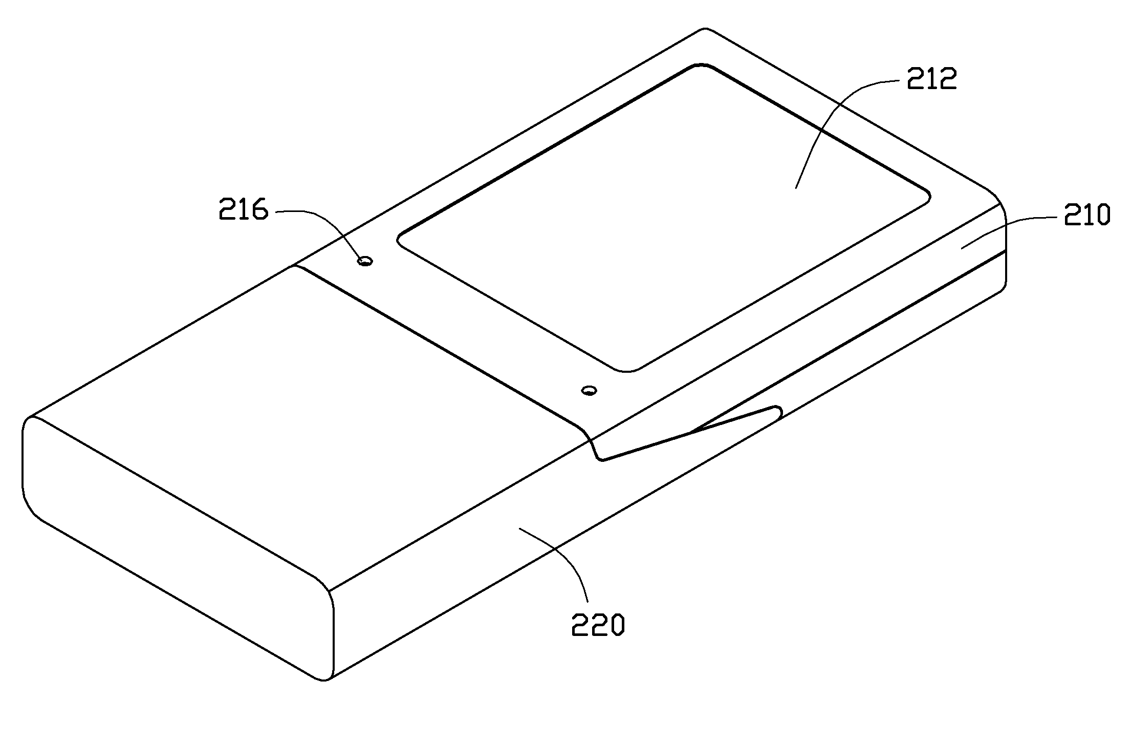
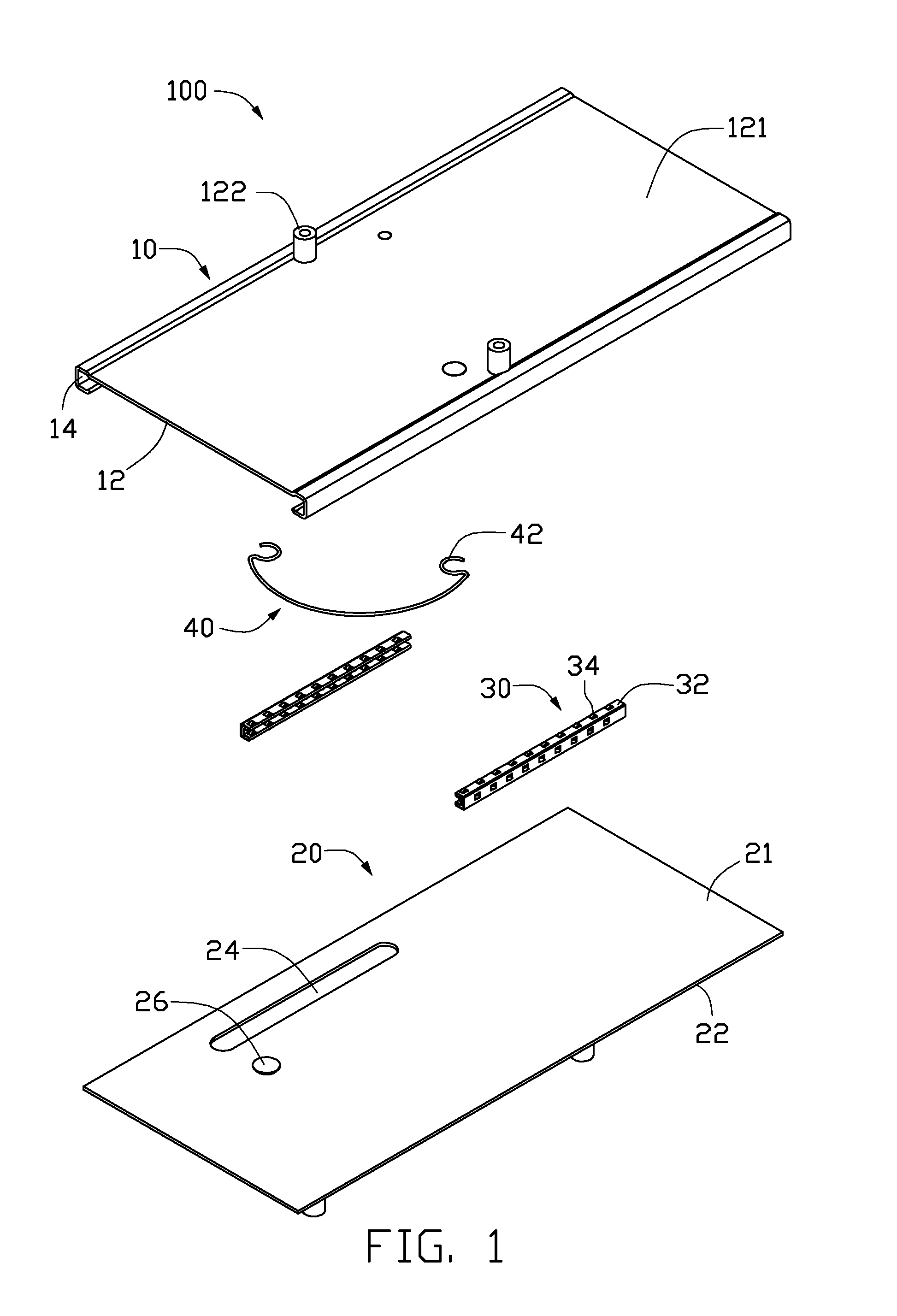
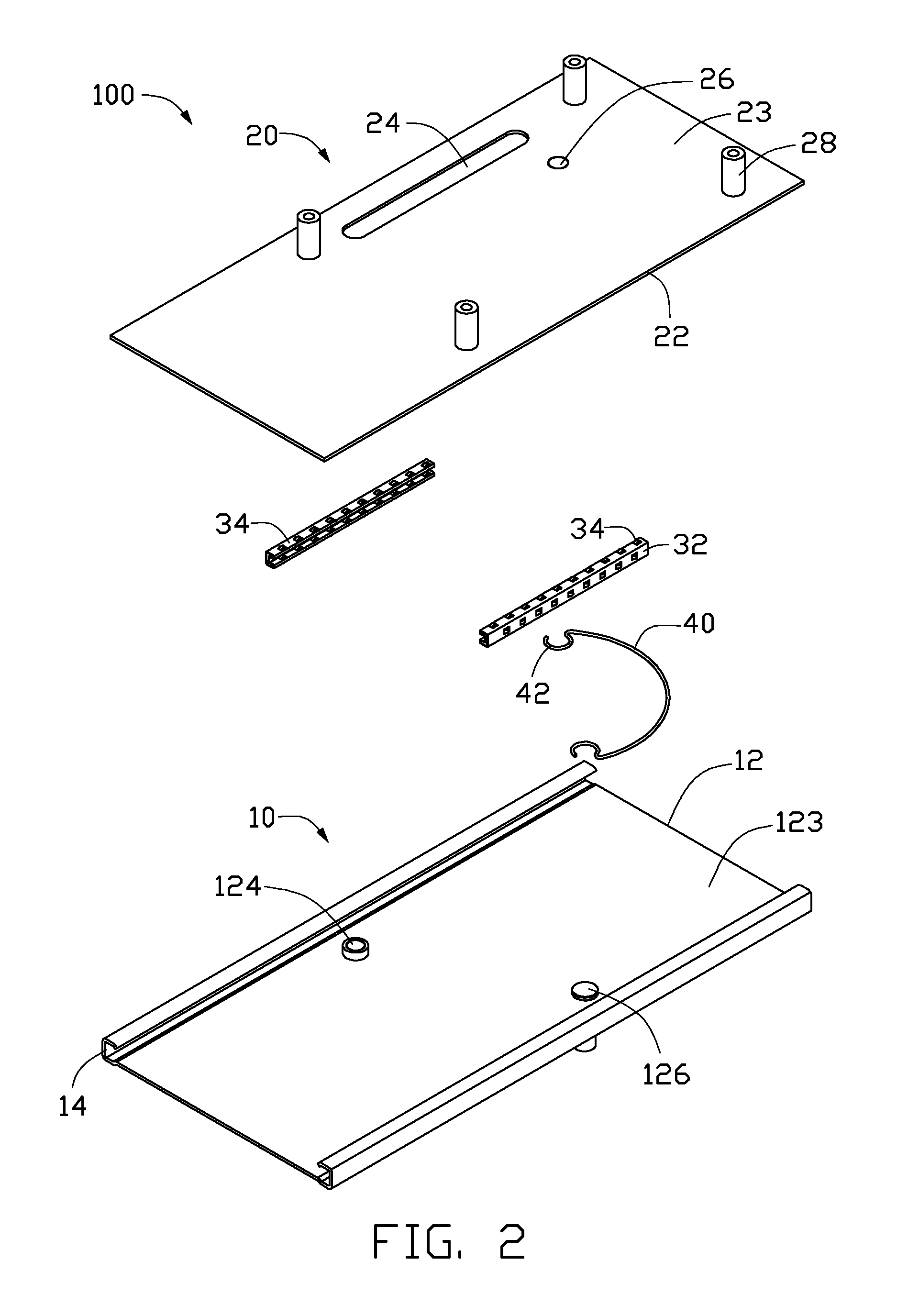
[0014]FIGS. 1 and 2 show a slide mechanism 100 used in a portable electronic device such as a mobile phone, a digital camera, etc. The slide mechanism 100 includes a main plate 10, a slide plate 20, two guide bodies 30 assembled in the main plate 10, and an elastic member 40 connected with the main plate 10 and the slide plate 20.

[0015]The main plate 10 includes a plate portion 12 and two guiding groove portions 14 at two sides of the plate portion 12. The plate portion 12 is substantially flat and includes an upper surface 121 and a lower surface 123. The upper surface 121 has two first connecting poles 122 protruding therefrom. Each of the first connecting poles 122 is adjacent to one of the two sides of the plate portion 12 and used to connect to a housing of an electronic device. The lower surface 123 has a guiding pole 124 and a first fixing pole 126 protruding therefrom. The guiding pole 124 is a column and located adjacent to a side of the plate portion 12. The first fixing p...


PUM


Abstract

A slide mechanism comprises a main plate forming two guiding groove portions, and a slide plate forming two guiding flanges engaging with the guiding groove portions respectively. The slide mechanism includes a plurality of rollers received in the guiding groove portions to guide the guiding flanges to slide relative to the guiding groove portions. The invention also discloses a portable electronic device applying the slide mechanism.

Description

BACKGROUND[0001]1. Technical Field[0002]The present disclosure generally relates to sliding mechanisms and, particularly, a sliding mechanism used in portable electronic devices.[0003]2. Description of Related Art[0004]Slide-type portable electronic devices have been increasingly popular among portable electronic devices. The slide-type portable electronic device generally includes two housings and a slide mechanism connected to the two housings, the slide mechanism can drive one of the housings to slide over the other to open / close the portable electronic device. The slide mechanism includes a slide plate and a main plate engaging with the slide plate. One of the slide plate and the main plate defines guiding grooves, and the other forms rails accordingly engaging with the guiding grooves.[0005]However, each of the rails is received in the corresponding guiding groove with the rail sidewall abutting the peripheral wall of the groove. The friction and the wearing of the rail sidewal...

Claims


Application Information

Patent Timeline
IPC IPC(8): H04M1/00
CPCF16C29/04H04M1/0237Y10T408/892Y10T408/567Y10T408/03Y10T408/556
Inventor PENG, ZHI-GANGSHI, ZHI-QIANG
Owner SHENZHEN FUTAIHONG PRECISION IND CO LTD
Features
  • R&D
  • Intellectual Property
  • Life Sciences
  • Materials
  • Tech Scout
  • Unparalleled Data Quality
  • Higher Quality Content
  • 60% Fewer Hallucinations
Learn More