

Conveyor system load transfer devices
- Summary
- Abstract
- Description
- Claims
- Application Information
AI Technical Summary
Benefits of technology
Problems solved by technology
Method used
Image

Examples
first embodiment
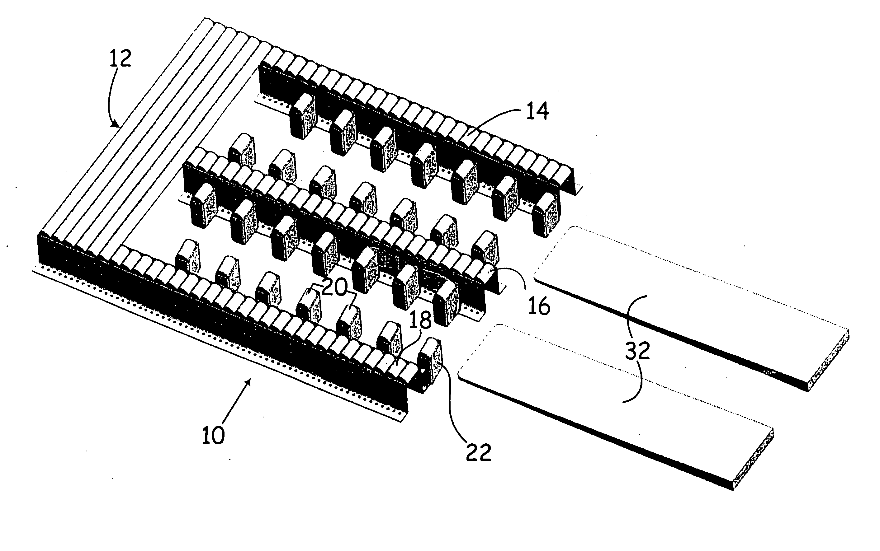
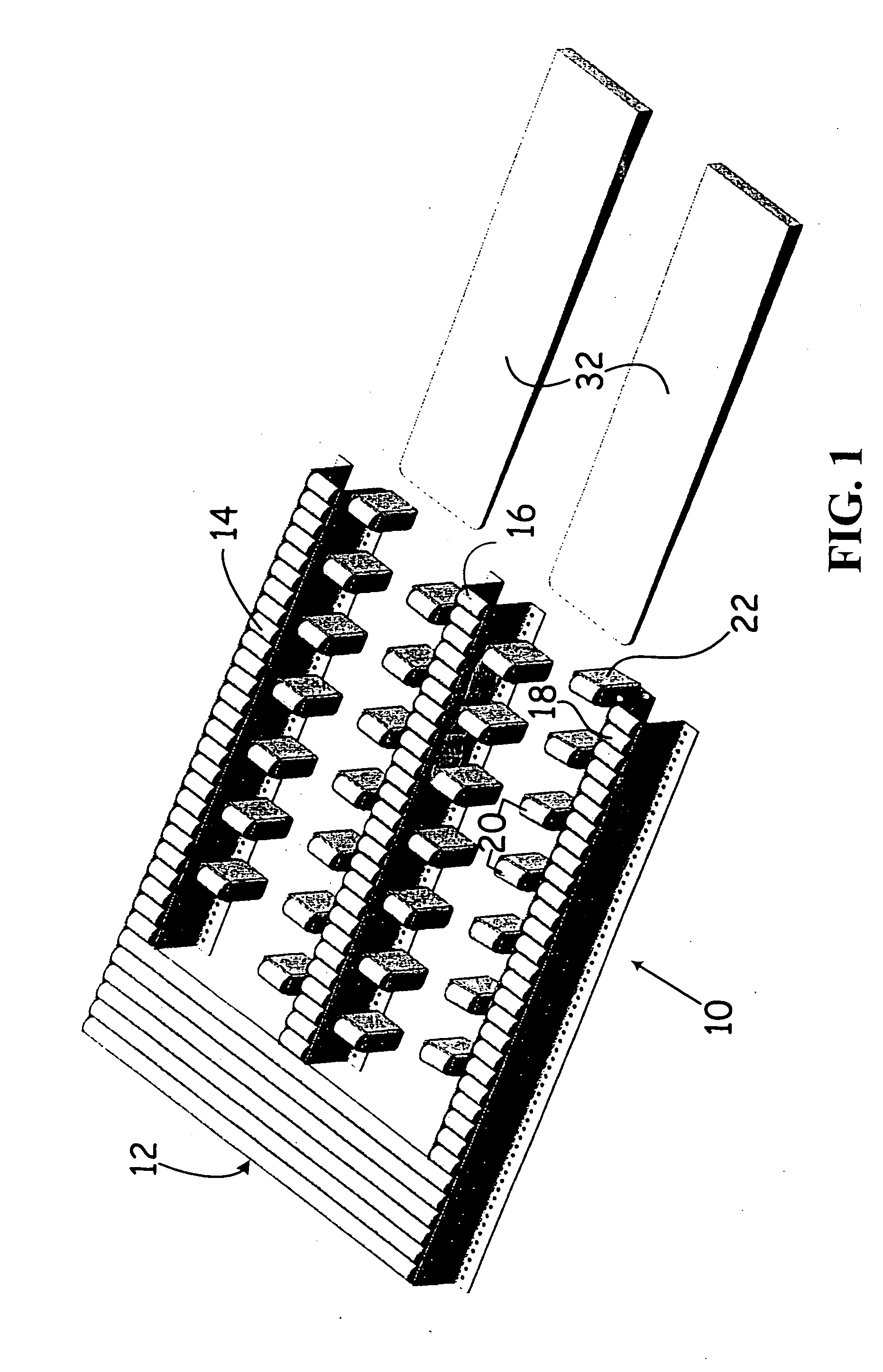
[0008] In the first embodiment of the transfer structure of this invention, illustrated in FIGS. 1, 2, and 3, the transfer structure comprises a generally rectangular structure approximating the size of a conventional slip sheet. The transfer structure, as may be seen in FIG. 1, includes: (1) fixed rollers positioned in the same plane as adjacent roller conveyor structure and (2) movable rollers that move, in response to the presence of lift truck platen, from a first position with the rollers in the same plane as the fixed rollers, to a second position that may or may not place the movable rollers in the same plane but that provides room for the lift truck platens.
[0009]FIGS. 1, 2, and 3 illustrate a first embodiment of this invention where the transfer structure 10 is mounted adjacent to conventional roller conveyor structure 12. As shown in FIG. 1, fixed rollers 14 and 18 are located at the side edges and middle of transfer structure 10. The tops of roller 14, 16, and 18 are in ...
second embodiment
[0013]FIGS. 4, 5, and 6 illustrate a second embodiment 50 of the transfer structure of this invention. In embodiment 50, hinged rollers 20 (structured in the same manner as hinged rollers 20 in embodiment 10 described above) are utilized. Fixed wheels 52 are located as illustrated in the center of embodiment 50 and, optionally, other fixed wheels or rollers (not shown) may be used, depending on the nature of the loads to be handled and their dimensions.
[0014] Embodiment 50 also utilizes two sections of rollers 54 and 56 mounted in a manner so that they are biased by a spring, pneumatic cylinder, or other suitable structure normally to be in the position shown in FIG. 4. However, sections of rollers 54 and 56 but may be caused to pivot downwards by platens 32 (not show in FIGS. 4, 5 and 6) so that platens 32 may lie on top of the sections of rollers 54 and 56.
[0015] In operation of this embodiment 50, the ends of platens 32 contact stop 58 as the platens move to the right in FIG. 4...
third embodiment
[0017]FIGS. 7, 8, and 9 illustrate a third embodiment 90 of the transfer structure of this invention together with a load mounted on a slip sheet schematically illustrated as a load 92. Transfer structure 90 utilizes relatively short fixed rollers 94, 96, and 98, mounted parallel to rollers 12 of a conventional conveyor structure. Sliding rollers 100 and 102 also mounted parallel to conventional rollers 12 are fixed in rack frames 104 and 106. Each of frames 104 and 106 is mounted, as may be best appreciated by reference to FIG. 8, to travel down and under rollers 12 to provide room for platens 32 (not shown) during transfer of a slip sheet mounted load. Roller racks 104 and 106 may, for instance, rest on wheels 108 that travel in tracks 110. Roller racks 104 and 106 are biased by springs, pneumatic cylinders, or other appropriate devices, to return to the positions illustrated in FIGS. 7 and 8 after platens 32 have moved away from the transfer structure 90.
[0018] As will be apprec...
PUM
 Abstract
Description
Claims
Application Information