
Slip sheet capture mechanism and method of operation

a technology of slip sheet and capture mechanism, which is applied in the field of slip sheet capture mechanism and method of operation, can solve the problems of preventing the establishment of predictable vacuum levels and not being compatible with all types of slip sheets

Inactive Publication Date: 2005-08-16
AGFA CORPORATIN
View PDF27 Cites 16 Cited by
  • Summary
  • Abstract
  • Description
  • Claims
  • Application Information

AI Technical Summary

Benefits of technology

"The invention is a mechanism for capturing and handling slip sheets in a substrate processing machine. It uses a foot and a nip roller to engage and draw the slip sheet into a nip, allowing for proper handling. The mechanism is compatible with different types of slip sheets, and a sensor is used to determine if a slip sheet is under the mechanism. The method involves holding a portion of the slip sheet and engaging and drawing it into the nip, which is then extracted from the machine. The technical effects of this invention include improved handling of slip sheets and compatibility with different types of slip sheets."

Problems solved by technology

The problem with this approach is that it is not compatible with all types of slip sheets.
This prevents the establishment of predictable vacuum levels that would ensure the proper handling of the slip sheets.

Method used


Image

  • Slip sheet capture mechanism and method of operation
  • Slip sheet capture mechanism and method of operation
  • Slip sheet capture mechanism and method of operation

Examples


Embodiment Construction

Plate Manager

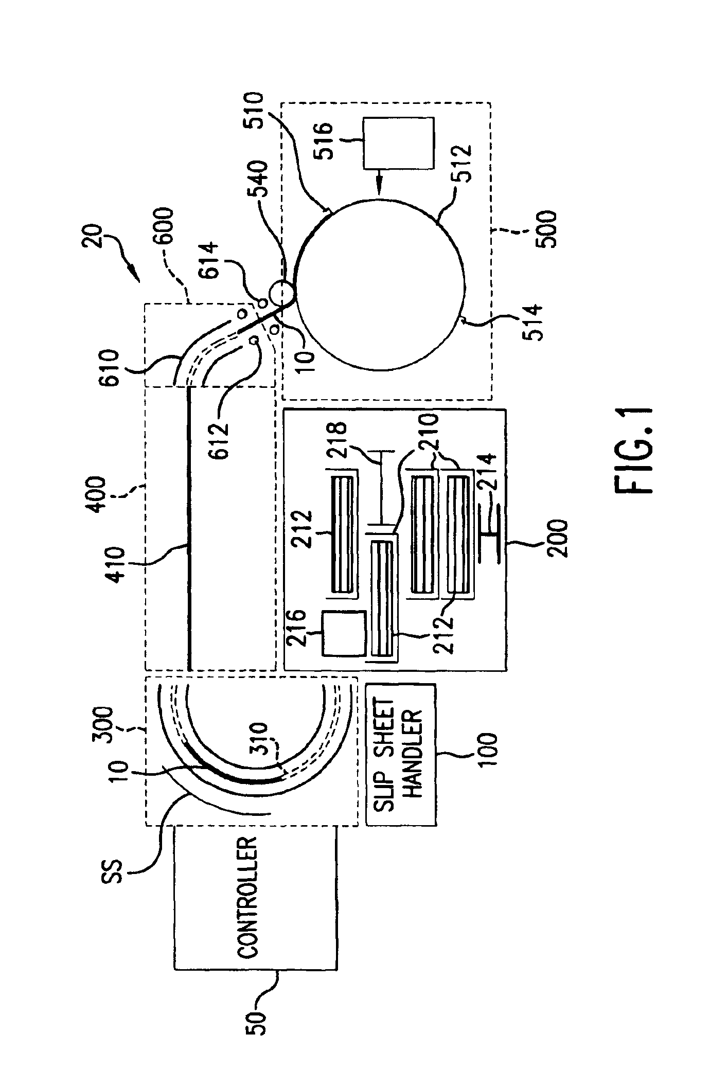
[0027]FIG. 1 shows a substrate, and more specifically a plate, manager 20, which has been constructed according to the principles of the present invention.

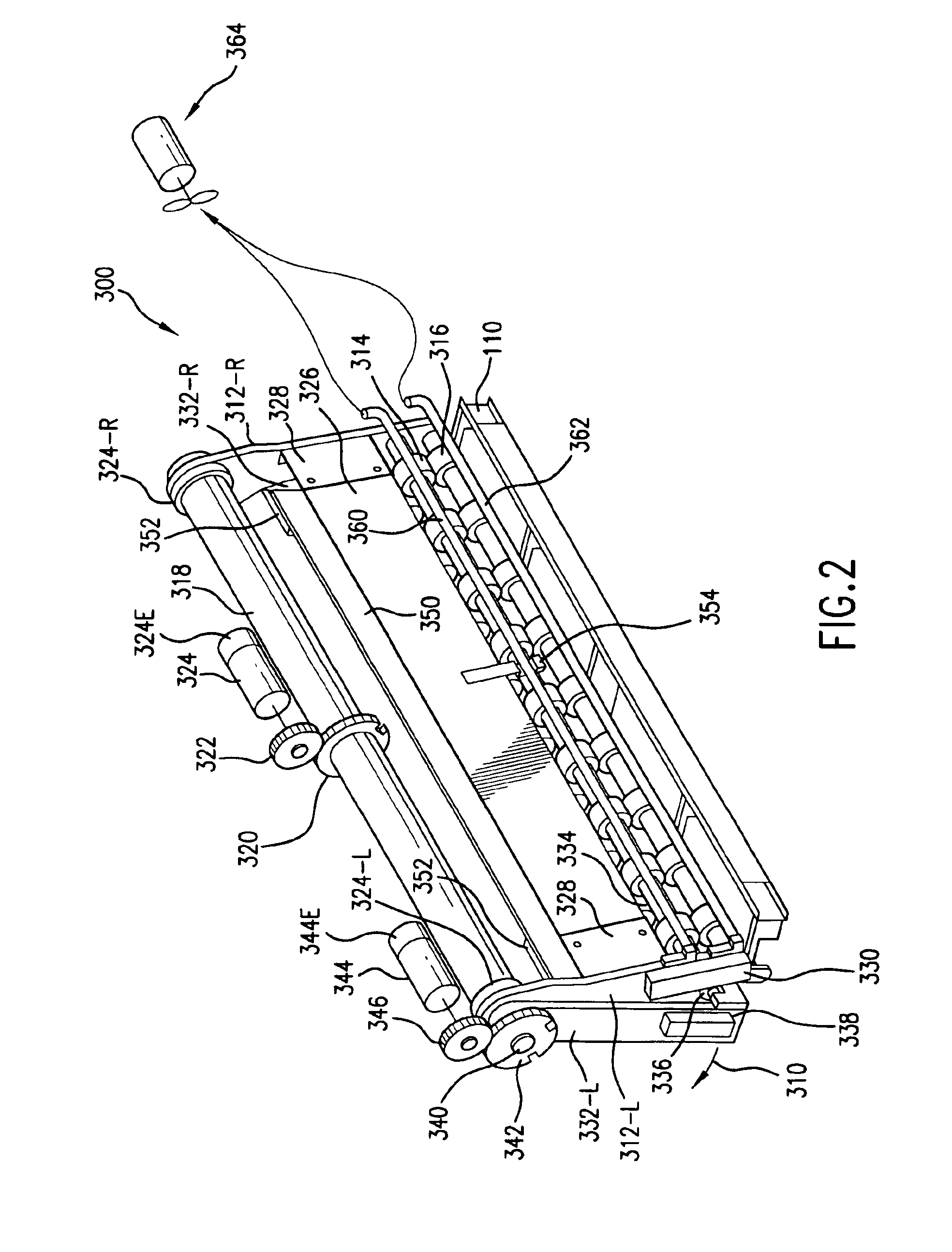
[0028]Generally, the plate manager 20 comprises a plate store 200, a plate inverter system 300, a plate transfer system 400, and a plate inserter 600, all of which are controlled by a system controller 50. A plate imaging engine 500 is further provided to expose the substrates.

[0029]The plate store system 200 comprises, when loaded, multiple cassettes 210. Each of these cassettes 210 holds a stack of plates 212. The cassettes are moved vertically within the plate store system 200 by a cassette elevator or lifter 214.

[0030]In one example, the cassettes themselves are stacked atop one another, or in stacks of cassettes, that are moved vertically by the cassette elevator 214 so that the stack of plates 212 of a specific cassette 210 is raised to the level of a plate picker system 216. Once the cassette 212 is at the prop...


PUM

PropertyMeasurementUnit
photosensitiveaaaaaaaaaa
vacuumaaaaaaaaaa
heightaaaaaaaaaa

Abstract

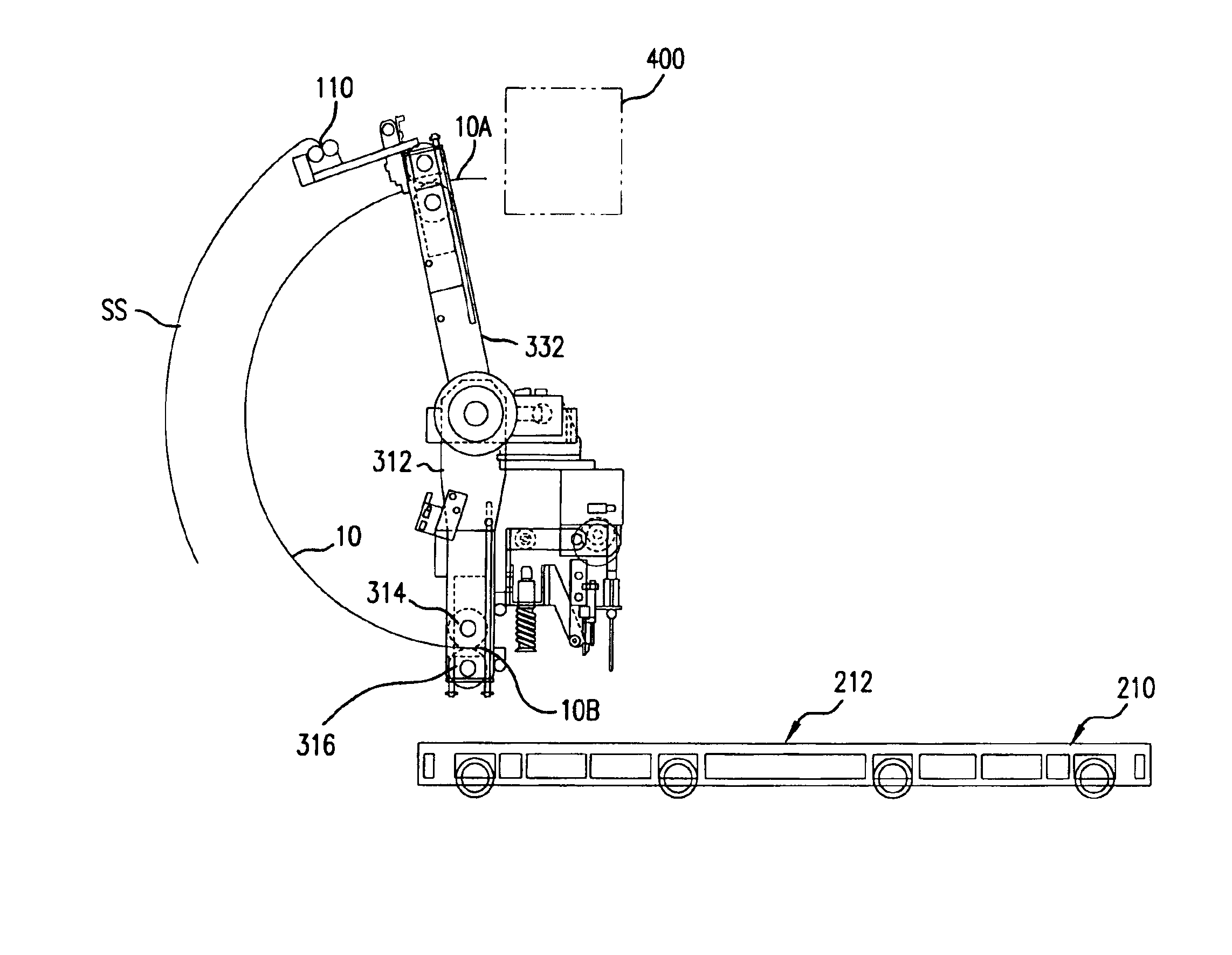
A substrate manager for a substrate exposure machine is used, in one example, as a platesetter. As such, it comprises a substrate storage system, containing one or more stacks of substrates, such as plates in one implementation. A substrate picker is provided for picking substrates from the stack of substrates. The substrates are then handed to a transfer system that conveys the substrates to an imaging engine. According to the invention, a substrate inverter system is also provided. This system inverts the substrates from being imaging or emulsion side down to emulsion side up in the present implementation. This allows plates, for example, which are stored emulsion side down in cassettes to be flipped to an emulsion side up orientation, and then transferred, using the substrate transfer system to the imaging engine. This flipping process has two advantages. First, the plates can be emulsion side up during the transfer. This prevents any damage to the sensitive plate emulsions. Moreover, the plates, now in an emulsion side up configuration are in the right orientation for being installed on the outside of a drum on an external drum imaging system, as is common in many platesetters. Also, the plates are picked from the non emulsion side. Thus the system is less sensitive to emulsion formulation changes. A slip sheet capture mechanism is also provided to pass slip sheets separating the plates to a storage location.

Description

BACKGROUND OF THE INVENTION[0001]Imagesetters and platesetters are used to expose substrates that are used in many conventional offset printing systems. Imagesetters are typically used to expose the film that is then used to make the plates for the printing system. Platesetters are used to directly expose the plates.[0002]For example, plates are typically large substrates that have been coated with photosensitive or thermally-sensitive material layers, referred to the emulsion. For large run applications, the substrates are fabricated from aluminum, although organic substrates, such as polyester or paper, are also available for smaller runs.[0003]Computer-to-plate printing systems are used to render digitally stored print content onto these printing plates. Typically, a computer system is used to drive an imaging engine of the platesetter. In a common implementation, the plate is fixed to the outside or inside of a drum and then scanned with a modulated laser source in a raster fash...

Claims


Application Information

Patent Timeline
Patent Type & Authority Patents(United States)
IPC IPC(8): B41C1/10B65H3/06G03F7/20B65H3/02B65H5/06B65H5/12
CPCB41C1/1083B65H3/02B65H2301/33216B65H2404/142B65H2405/51B65H2405/57B65H2511/51B65H2701/18264B65H2701/1928B65H2220/03B65H2220/01
Inventor RICHARDSON, JR., DONALD B.LYONS, JR., JOSEPH R.DASILVA, STEVEN J.
Owner AGFA CORPORATIN
Learn More