
Apparatus and method for transmission of dynamic feedback channel information in a MIMO system

a dynamic feedback and antenna system technology, applied in the field of antenna system transmission in a multiple input multiple output (mimo) antenna system, can solve the problems of ineffective method, high complexity, and inability to achieve the desired effect of method,

Active Publication Date: 2010-04-15
SEOUL NAT UNIV R&DB FOUND +1
View PDF42 Cites 7 Cited by
  • Summary
  • Abstract
  • Description
  • Claims
  • Application Information

AI Technical Summary

Benefits of technology

[0028]In another general aspect, a data transmission method of transmitting data to wireless terminals from a base station may further include determining a specific second quantization length as “0” when the specific second quantization

Problems solved by technology

A MIMO system having multiple users requires scheduling that enables multiple users to simultaneously communicate and is highly complex because each user's quality of service (QoS) requirements are considered.
This method, however, can be considered ineffective because it wastes wireless resources.
This method is not desirable, however, because the feedback information is increased.

Method used


Image

  • Apparatus and method for transmission of dynamic feedback channel information in a MIMO system
  • Apparatus and method for transmission of dynamic feedback channel information in a MIMO system
  • Apparatus and method for transmission of dynamic feedback channel information in a MIMO system

Examples


Embodiment Construction

[0039]The following detailed description is provided to assist the reader in gaining a comprehensive understanding of the methods, apparatuses and / or systems described herein. Accordingly, various changes, modifications, and equivalents of the systems, apparatuses and / or methods described herein will be suggested to those of ordinary skill in the art. Also, descriptions of well-known functions and constructions are omitted to increase clarity and conciseness.

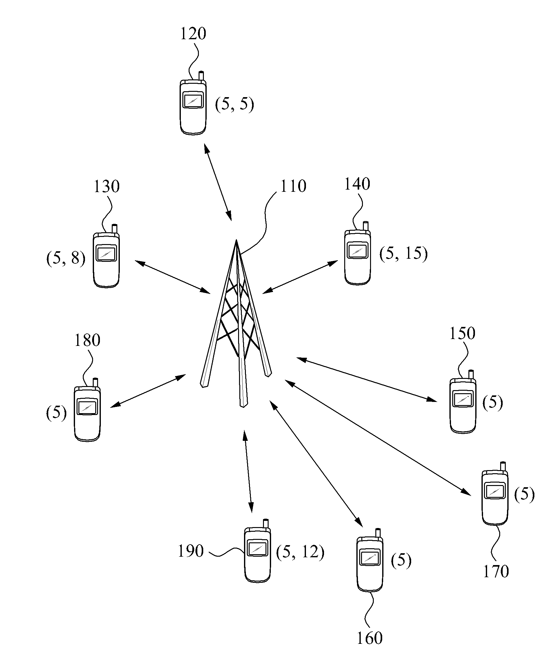
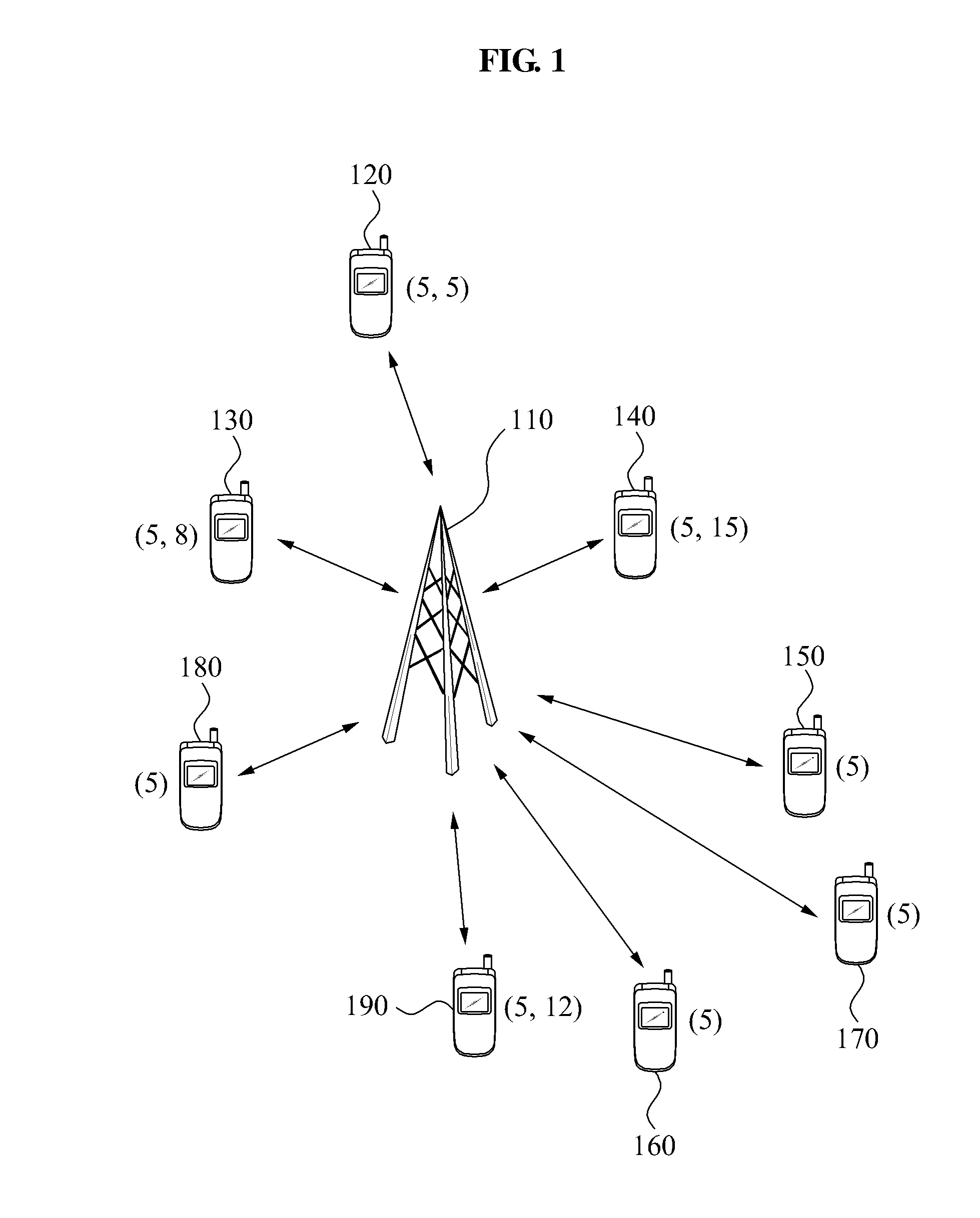
[0040]FIG. 1 is a diagram illustrating transmission of dynamic channel information in an exemplary MIMO wireless communication system. A plurality of terminals 120, 130, 140, 150, 160, 170, 180, and 190 may transmit channel information to a base station apparatus 110. The channel information may include wireless channel information from the base station apparatus 110 to each terminal 120, 130, 140, 150, 160, 170, 180, and 190.

[0041]Each terminal 120, 130, 140, 150, 160, 170, 180, and 190 may quantize a channel state information ...


PUM


Abstract

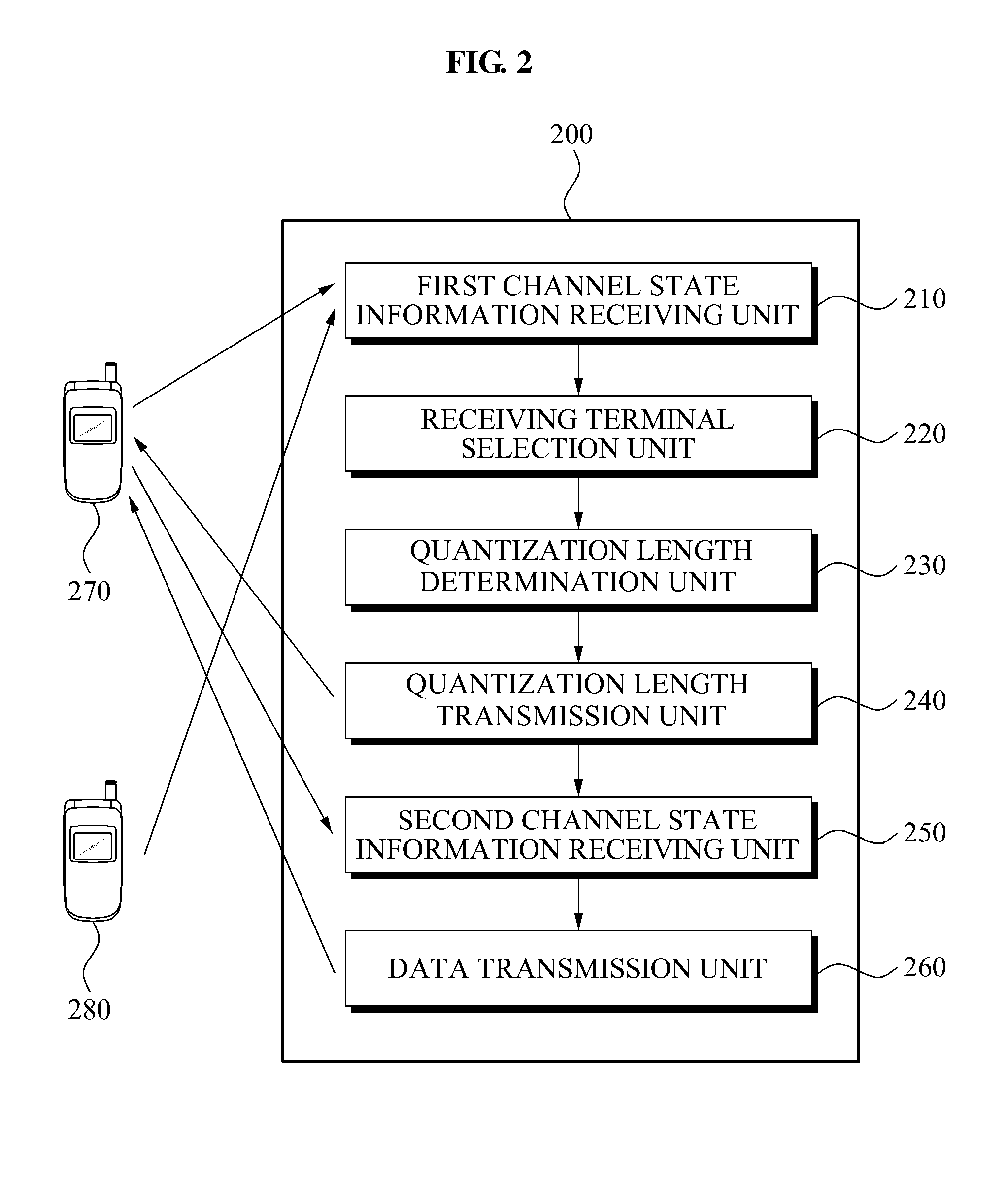
A base station apparatus and method of transmission of dynamic feedback channel information in a MIMO system. The base station apparatus includes a first channel state information receiving unit to receive a first channel state information; a receiving terminal selection unit to select at least one receiving terminal to receive data from among a plurality of terminals; a quantization length determination unit to independently determine a second quantization length of the selected receiving terminal; a quantization length transmission unit to transmit the second quantization length to the selected e receiving terminal; a second channel state information receiving unit to receive second channel state information from the selected receiving terminal; and a data transmission unit to transmit data to the selected receiving terminal using a plurality of transmission antennas of a base station based on the second channel state information.

Description

CROSS-REFERENCE TO RELATED APPLICATION[0001]This application claims the benefit under 35 U.S.C. § 119(a) of a Korean Patent Application No. 10-2008-0100077, filed Oct. 13, 2008, in the Korean Intellectual Property Office, the entire disclosure of which is incorporated herein by reference.BACKGROUND[0002]1. Field[0003]The following description relates to transmission in a multiple-input multiple-output (MIMO) antenna system. More particularly, the description relates to an apparatus and method of transmission of dynamic feedback channel information in a MIMO system.[0004]2. Description of Related Art[0005]A multiple input multiple output (MIMO) antenna system is a system where a plurality of antennas are located in a transmitter and each antenna independently transmits information to a receiver. Such systems are referred to as a MIMO system or a space division multiplexing (SDM) system. The MIMO antenna system is a system which utilizes a spatial area to enable high speed data transm...

Claims


Application Information

Patent Timeline
IPC IPC(8): H04W72/04
CPCH04W72/0406H04W72/085H04W72/046H04W72/20H04W72/542H04B1/76H04B7/0413H04B7/0626H04W88/02
Inventor SOHN, III SOOLEE, KWANG BOKPARK, CHANG SOONKIM, SUNG JIN
Owner SEOUL NAT UNIV R&DB FOUND
Learn More