Indirect Fluid Flow Measurement

Active Publication Date: 2010-04-15
MINERVA SURGICAL
View PDF6 Cites 17 Cited by
  • Summary
  • Abstract
  • Description
  • Claims
  • Application Information

AI Technical Summary

Benefits of technology

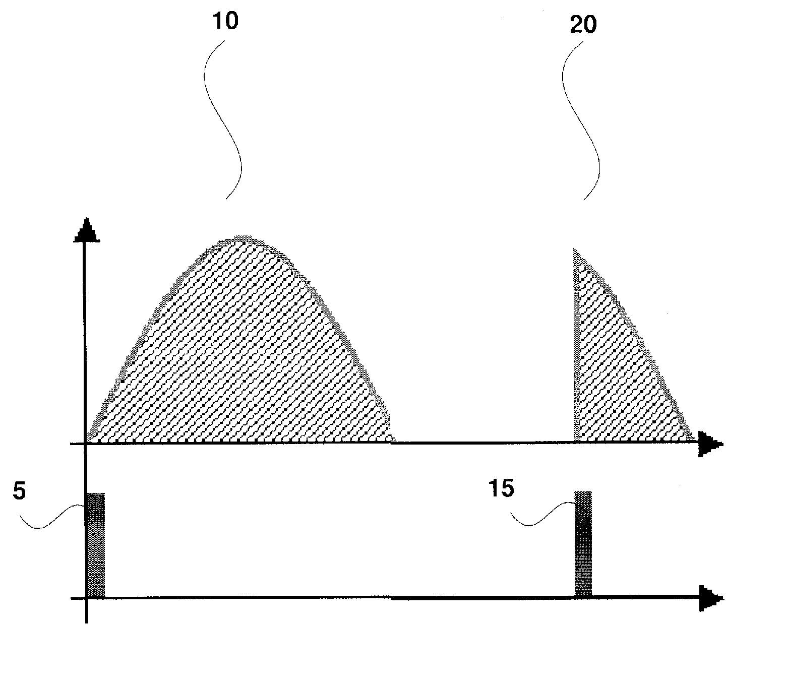
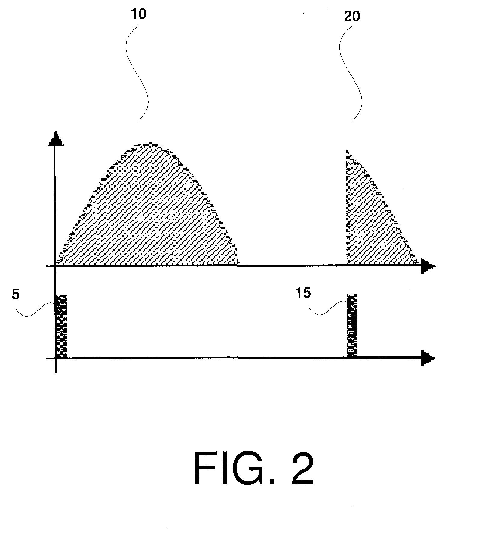
[0004]The present invention is directed to a method for ablating tissue comprising controlling a heating element using a variable phase angle control to heat an ablation fluid to a desired temperature and determining a heating percentage corresponding to a percentage of a maximum available heating power represented by a current level of power supplied to the heating element and, when the heating percentage remains below a threshold level for a predetermined period of time, indicating a flow obstruction condition of the fluid.
[0005]The pres

Problems solved by technology

Undesirable circulating fluid levels and flow rates may prevent the heated fluid fro

Method used


Image

  • Indirect Fluid Flow Measurement
  • Indirect Fluid Flow Measurement
  • Indirect Fluid Flow Measurement

Examples


Embodiment Construction

[0009]The present invention may be further understood with reference to the following description. The present invention relates to a system and method for regulating fluid flow and fluid level within a device for thermally ablating tissue, e.g., tissue lining an inner surface of a hollow organ. In particular, the present invention relates to devices for ablating the endometrium. However, those skilled in the art will understand that the present invention, and / or components thereof, may be utilized in conjunction with devices for prostate treatment (microwave or cyroablation), irrigation systems or other devices for procedures which infuse heated fluids to the body.

[0010]Fluid ablation systems generally utilize one or more resistive heating elements to warm a circulating fluid (e.g., saline) to a predetermined, substantially constant temperature. For example, such a thermal ablation system may heat the ablation fluid within a disposable cassette portion which is removably coupled to...


PUM


Abstract

A method for ablating tissue comprising controlling a heating element using a variable phase angle control to heat an ablation fluid to a desired temperature and determining a heating percentage corresponding to a percentage of a maximum available heating power represented by a current level of power supplied to the heating element and, when the heating percentage remains below a threshold level for a predetermined period of time, indicating a flow obstruction condition of the fluid.

Description

PRIORITY CLAIM[0001]This application claims the priority to the U.S. Provisional Application Ser. No. 61 / 017,426, entitled “Indirect Fluid Flow Measurement” filed on Dec. 28, 2007. The specification of the above-identified application is incorporated herewith by reference.FIELD OF THE INVENTION[0002]The present invention relates to systems and methods for determining a rate of fluid flow through an ablation device.BACKGROUND[0003]One technique for the treatment of menorrhagia relates to the ablation of uterine lining using heated fluid which is withdrawn via a return lumen. Such systems are heavily reliant on the maintenance of substantially constant circulating fluid level and flow rate within the uterus to ensure the safety, efficiency and effectiveness of the treatment. Undesirable circulating fluid levels and flow rates may prevent the heated fluid from reaching and properly ablating the entire surface area of the lining of the uterus.SUMMARY OF THE INVENTION[0004]The present in...

Claims


Application Information

Patent Timeline
IPC IPC(8): A61B18/04
CPCA61B2018/00702A61B2018/0075A61B2018/00779A61B2018/00791A61B2018/00797A61B2018/00666A61B2018/046A61B18/04A61B2018/00577A61B2018/00642A61B2018/00815
Inventor BOUTHILLIER, ROBERT J.JARVA, CURTISKEANEY, STEPHEN S.SHAPETON, BORISWYER, JORAH
Owner MINERVA SURGICAL
Why Eureka
Try Eureka