Control device setting method and program

a technology of control device and program, applied in the field of control device setting method and program, can solve the problems of unauthorized user access, complicated work procedure especially, complicated work procedure,

Active Publication Date: 2010-04-15
KONICA MINOLTA BUSINESS TECH INC
View PDF16 Cites 11 Cited by
  • Summary
  • Abstract
  • Description
  • Claims
  • Application Information

AI Technical Summary

Benefits of technology

[0012]1. A computer readable recording medium which stores installer building software for building installer s

Problems solved by technology

To ensure output from a plurality of image forming apparatuses linked to the network, a plurality of printer drivers must be installed and this involves complicated work procedures.
This will involve a complicated work procedure especially for those not fully familiar with the work.
Thus, an unauthorized user may access the apparatus, for example, and such secur

Method used


Image

  • Control device setting method and program
  • Control device setting method and program
  • Control device setting method and program

Examples


example 1

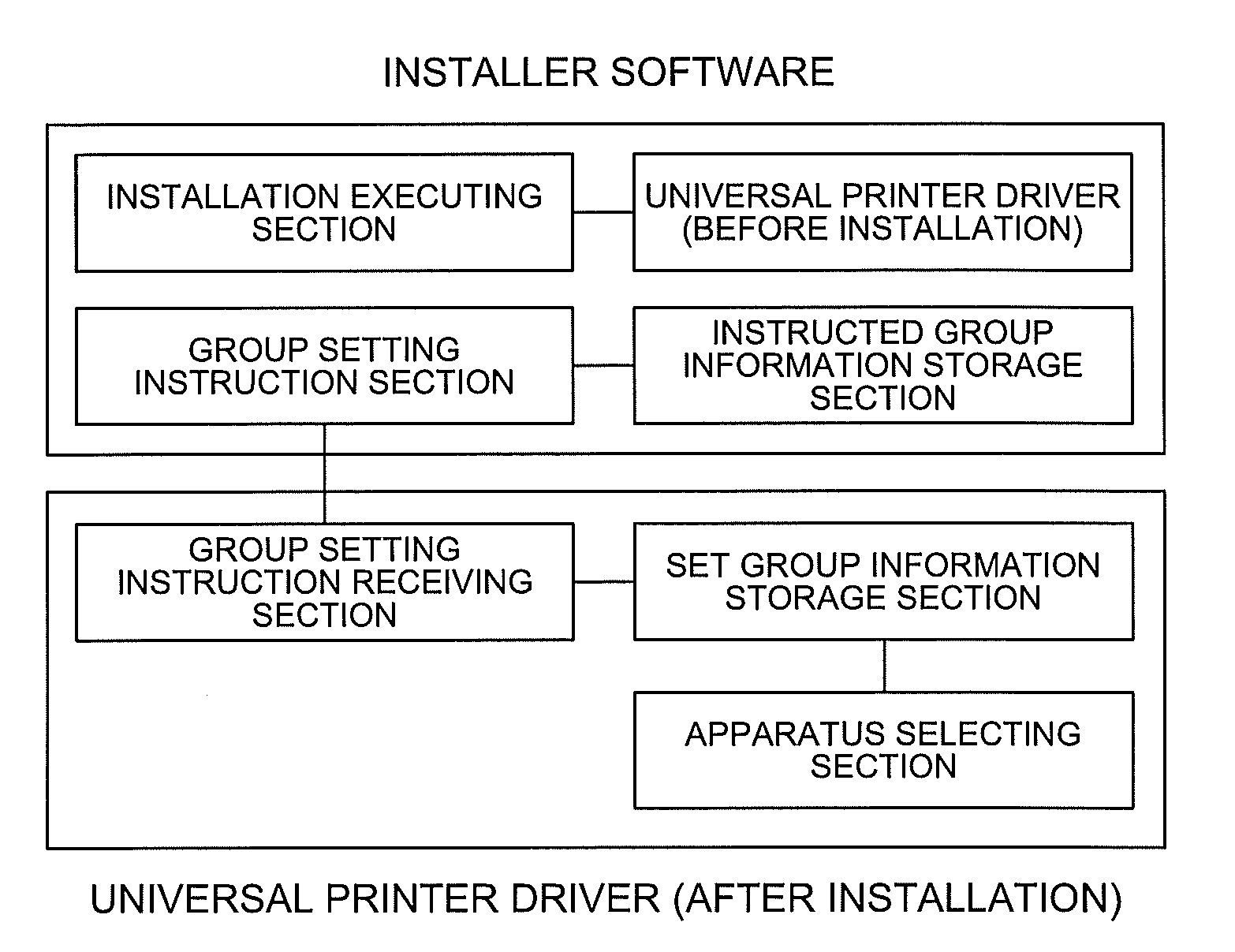
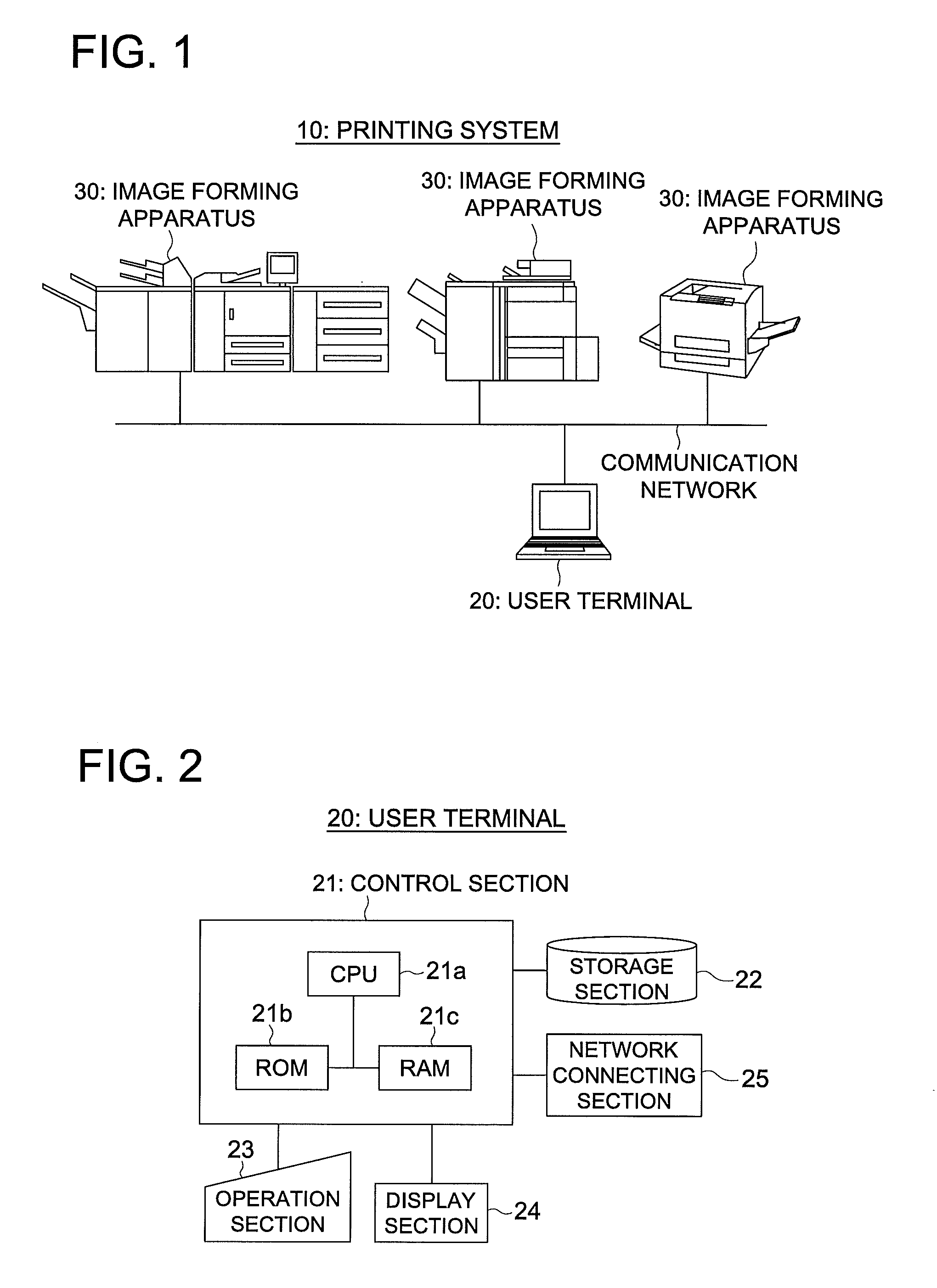
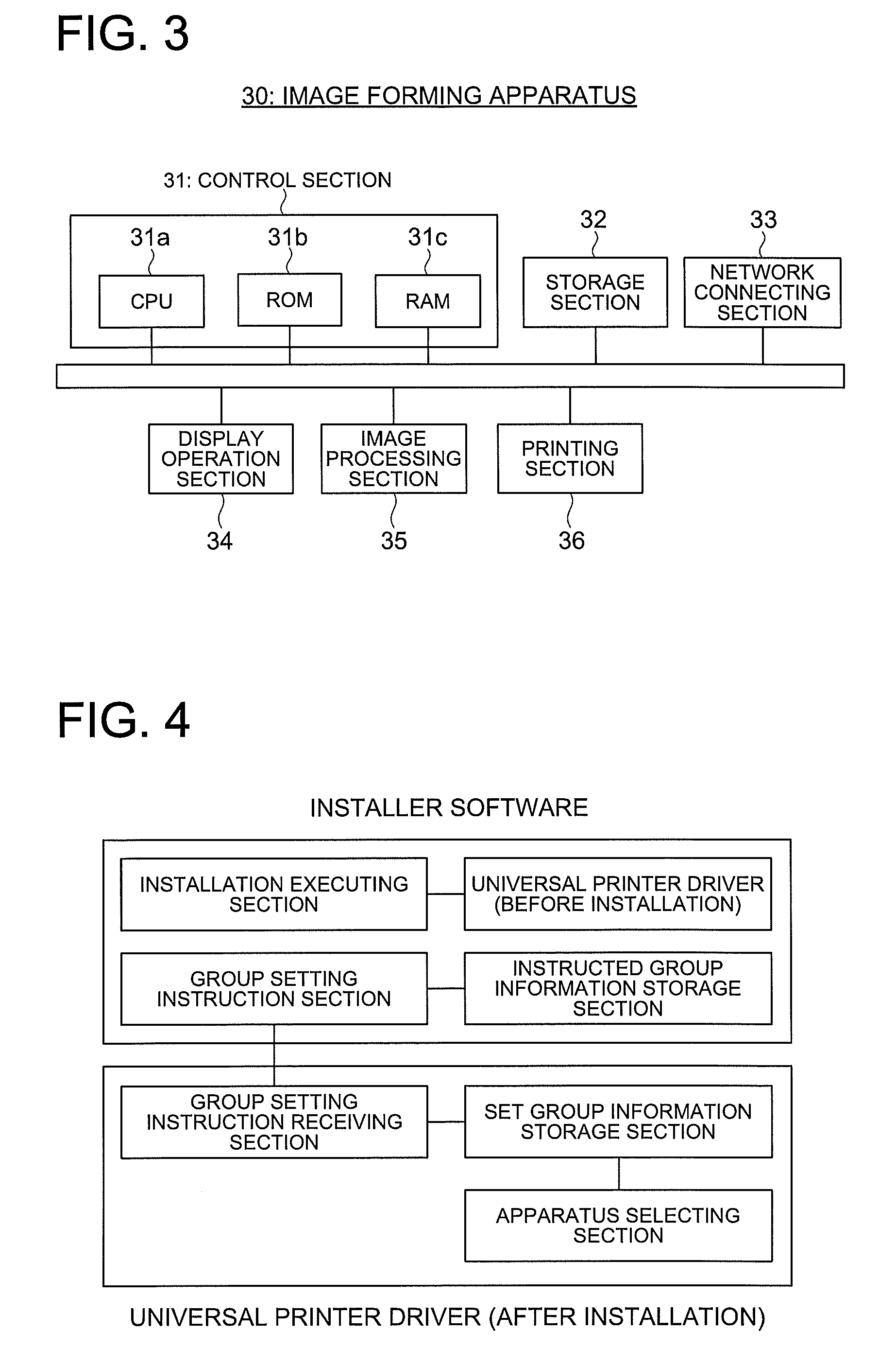
[0051]To show one embodiment of the aforementioned present invention in greater detail, the following describes the control device setting method and program of a first example of the present invention with reference to FIGS. 1 through 10. FIG. 1 is a diagram schematically representing the structure of a printing system in the present example. FIG. 2 is a block diagram representing the structure of a user terminal. FIG. 3 is a block diagram representing the structure of an image forming apparatus. FIG. 4 is a block diagram representing the functions of the universal printer driver and installer software. FIG. 5 is a block diagram representing the function of the installer building software. FIGS. 6 through 8 are the flow charts representing the control procedure in the user terminal in the present example. FIGS. 9 and 10 are diagrams showing examples of the structures of the screens displayed on a display section in the user terminal.

[0052]As shown in FIG. 1, the printing system 10 ...

example 2

[0108]The control device setting method and program of the second Example of the present invention will be described with reference to FIG. 11. FIG. 11 shows an example of the structure of the screen displayed on the display section of the user terminal. In this Example, the description of the same components as those of the first Example will be omitted, and only the differences will be described.

[0109]In the aforementioned first Example, display is given in such a way that the same printers can be selected by the universal printer driver installed in each user terminal 20, though different printers are suited for the output, depending on the organizational division and post of the user as well as the location of the user terminal 20. Thus, in this Example, the range of the printer selection for each user can be changed when the universal printer driver is installed.

[0110]The basic structure of the printing system in this case and the building configuration procedure of the install...

example 3

[0136]Referring to FIG. 12, the following describes the control device setting method and program of a third Example of the invention. FIG. 12 is a diagram schematically representing the structure of a printing system of the third example of the present invention. In this Example as well, the description of the same components as those of the first and second Examples will be omitted, and only the differences will be described.

[0137]In the aforementioned first and the second Examples, arrangements are made in such a way that the group information is registered in the installer software using the user terminal 20 of the administrator. In this case, to update the group information, the installer software must be re-built. Thus, this Example proposes a method of permitting the group information to be updated, without having to re-build the installer software.

[0138]As shown in FIG. 12, the printing system of this Example includes a user terminal 20, image forming apparatus 30 and server...


PUM


Abstract

Execution is provided of at least: the first processing for making the installer software store the group information that relates to information which classifies a plurality of apparatuses into groups and specifies the apparatuses belonging to each group or the address information indicating the location storing this group information, at the time of building the installer software for installing the universal control software that provides universal control of a plurality of the apparatuses; the second processing for notifying about the group information or address information to prompt the group setting of a plurality of the apparatuses when installing the universal control software using installer software; and the third processing for selecting an apparatus as the object of control from among the apparatuses specified by group information acquired from the storage location having been notified or specified by the address information, when universal control software is executed.

Description

[0001]This application is based on Japanese Patent Application No. 2008-263886 filed on Oct. 10, 2008 with Japanese Patent Office, the entire content of which is hereby incorporated by reference.BACKGROUND OF THE INVENTION[0002]The present invention relates to a control device setting method and program, particularly to a method and program for setting, out of a plurality of apparatuses on the network, a group of image forming apparatuses from which an object of control is to be chosen.[0003]In recent years, there has been a widespread use of printing apparatuses such as printers and digital multi-functional peripherals (hereinafter referred to as “image forming apparatuses”). When the image forming apparatus as a network printer is used to perform printing, a document is created by using the document creating application installed in the user terminal linked with the network, and is converted into the print data in the form of PDL (Page Description Language), using the software (pr...

Claims


Application Information

Patent Timeline
IPC IPC(8): G06F9/445
CPCG06F3/1204G06F3/1218G06F3/1239G06F3/1228G06F3/1225
Inventor HARADA, SEIJI
Owner KONICA MINOLTA BUSINESS TECH INC
Why Eureka
Try Eureka