Impingement Cooling

a cooling and impingement technology, applied in cooling/ventilation/heating modification, semiconductor devices, lighting and heating apparatus, etc., can solve the problems of increasing component power dissipation and approaching the effective limit of pcb

Inactive Publication Date: 2010-04-22
ADVANCED THERMAL SOLUTION
View PDF7 Cites 28 Cited by
  • Summary
  • Abstract
  • Description
  • Claims
  • Application Information

AI Technical Summary

Problems solved by technology

With an increase in component power dissipation and shrinking real estate on a printed circuit board (PCB) for a heat sink, conventional air cooling by forcing air substantially parallel to the PCB is approaching its effective limit.

Method used


Image

  • Impingement Cooling
  • Impingement Cooling
  • Impingement Cooling

Examples


Embodiment Construction

[0028]The present disclosure relates to a system and method for cooling electric and electronic equipment.

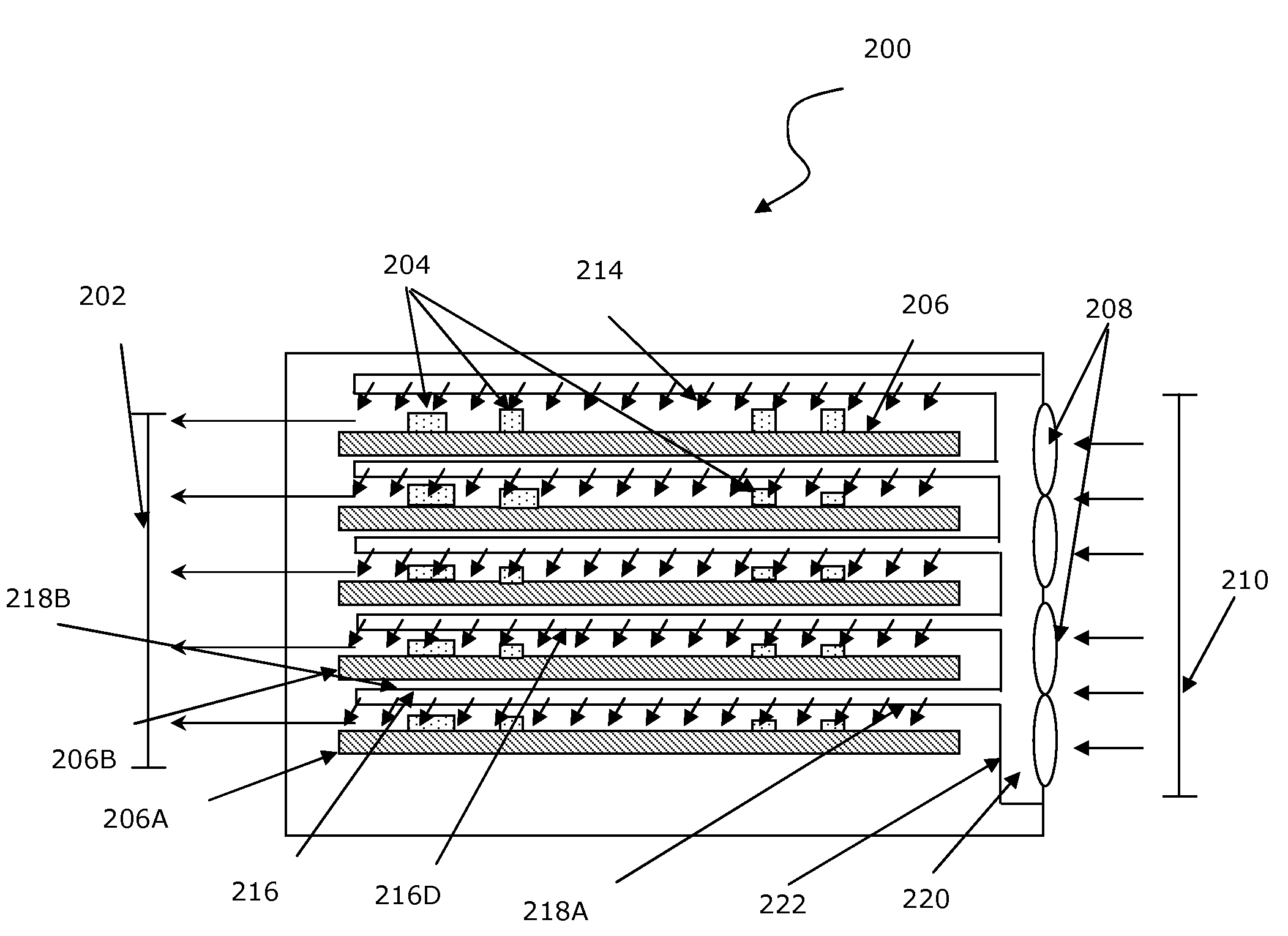
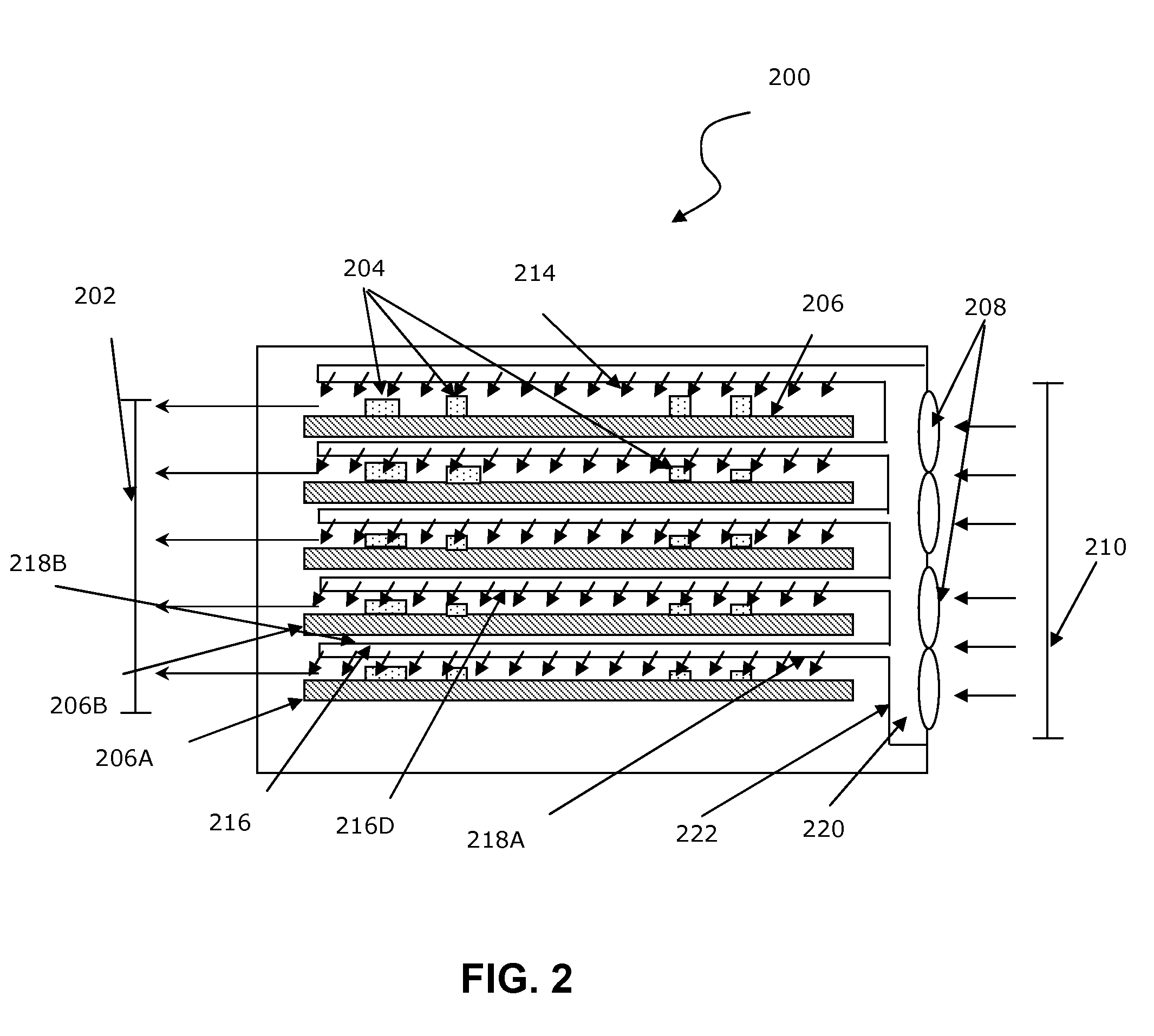
[0029]FIG. 2 is a cross-section view of an embodiment of the present disclosure. FIG. 2 illustrates a system 200 which may include an apparatus having a plenum 220. An example of the system 200 may be a 5-slot ATCA. The plenum 220 may have a fluid, such as an input air 210, forced through a fan 208 (a pair of fans 208 shown) and the plenum 220 may be configured to contact a plate 222. A duct 216, such as an impingement duct, may be attached to the plate 222, wherein the duct 216 may include a hole configured to pass the input air 210. The hole, more clearly shown in FIG. 6 described below, may be in an impingement plate, described below, included in the duct. The holes 940, 1040, 1140, 1240, and 1340 are more clearly shown in FIGS. 9-13 described below. A heat source, such as a component 204 being of an electric or electronic type, may be located proximate to the hole and the ho...


PUM


Abstract

An apparatus and a method for impingement cooling. The apparatus may include a plenum having a fluid. The plenum may be configured to contact a plate. A duct may be attached to the plate, wherein the duct may include a hole configured to pass the fluid, such as an air or a gas. A heat source, such as an electric or electronic component, may be located proximate to the hole, such as on a printed circuit board. The hole may be configured to make a contact between the fluid and the heat source. Methods to make the foregoing structure are also described.

Description

BACKGROUND[0001]1. Field[0002]This disclosure is generally related to impingement cooling and in particular to impingement cooling of electric and electronic circuits, such as electric and electronic circuits located in an enclosure.[0003]2. Description of Related Art[0004]Typical electronic circuitry requires some form of cooling to avoid component damage or premature component failure. With an increase in component power dissipation and shrinking real estate on a printed circuit board (PCB) for a heat sink, conventional air cooling by forcing air substantially parallel to the PCB is approaching its effective limit.[0005]FIG. 1 is a cross-section view of a prior art apparatus 100 for cooling an electronic equipment. The apparatus 100 is a 5 slot ATCA (Advanced Telecom Computing Architecture) chassis. Input air 110 is drawn by one or more fans 108 (two fans shown in FIG. 1). Air 112 is shown in contact with components 104 attached to a printed circuit board (PCB) 106. Exhaust air 10...

Claims


Application Information

Patent Timeline
Patent Type & Authority Applications(United States)
IPC IPC(8): H05K7/20F28D15/00
CPCH01L23/4735H05K7/20145H01L2924/0002H01L2924/00H05K7/20563
Inventor AZAR, KAVEHTAVASSOLI HOJATI, BAHMAN
Owner ADVANCED THERMAL SOLUTION
Why Eureka
Try Eureka