
Micro-Vitreoretinal Trocar Blade

a micro-vitreoretinal and trocar blade technology, applied in the field of tissue incision, can solve the problems of short blade width, reduced incision width, complicated procedure for inserting trocar cannula, etc., and achieve the effect of maximizing incision width and maximizing incision width

Inactive Publication Date: 2010-04-22
ALCON RES LTD
View PDF10 Cites 4 Cited by
  • Summary
  • Abstract
  • Description
  • Claims
  • Application Information

AI Technical Summary

Benefits of technology

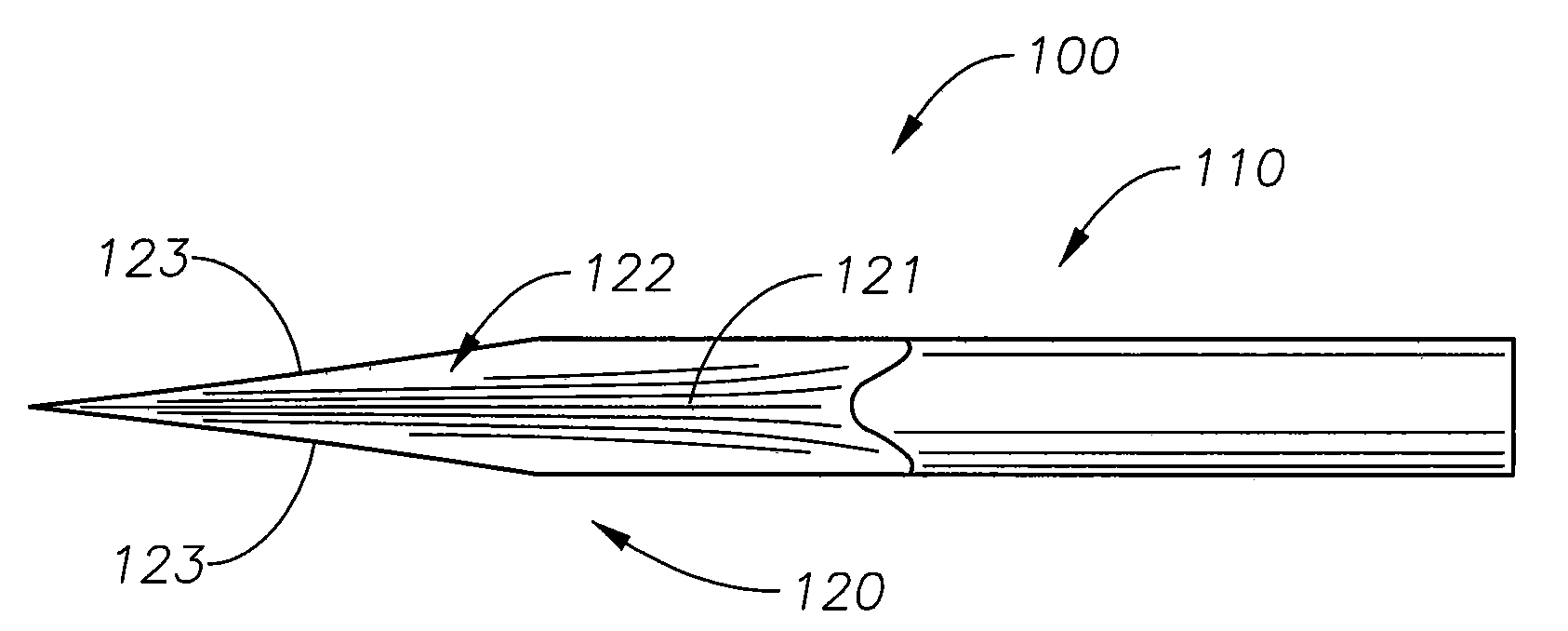
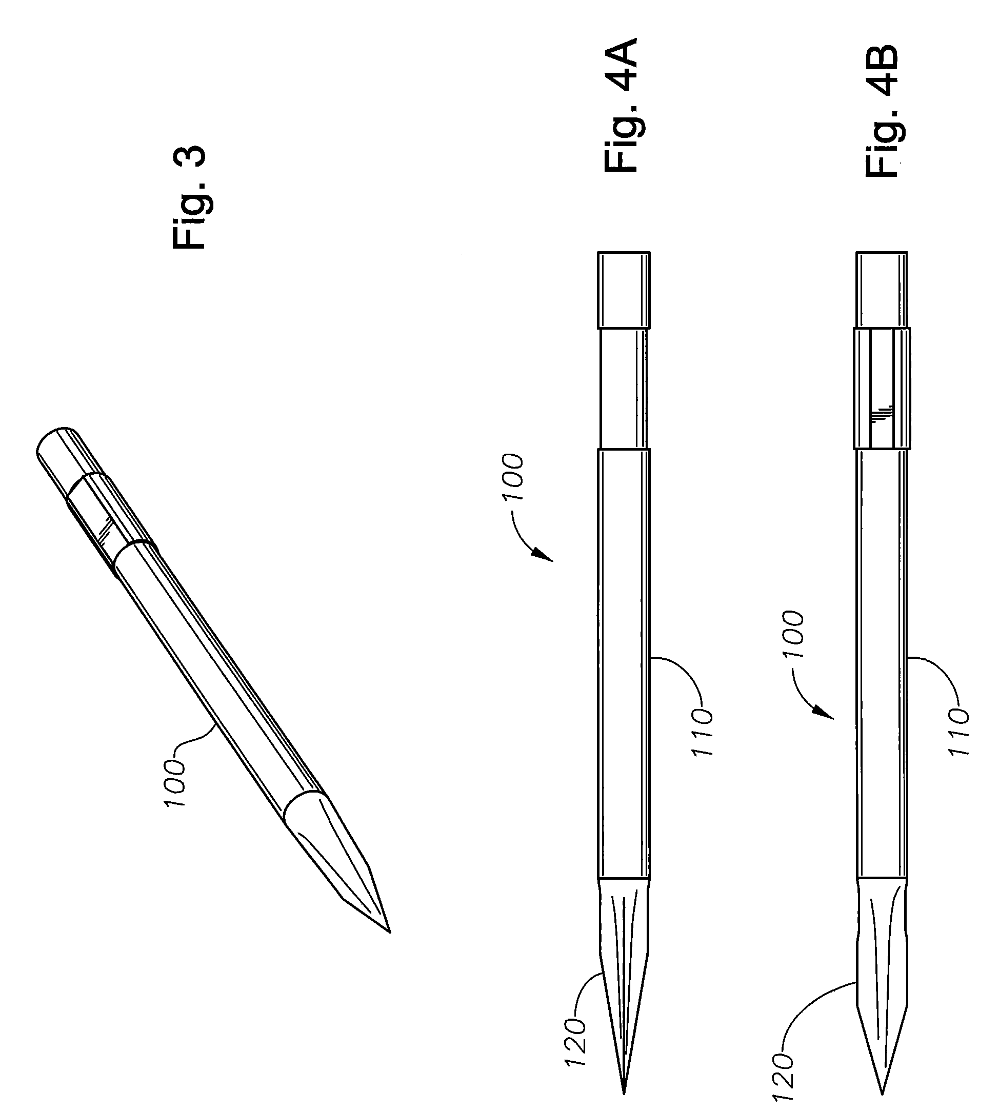
[0004]Embodiments of a micro-vitreoretinal trocar blade disclosed herein may utilize a blade geometry to produce a linear incision in tissue and maximizing incision width. In some embodiments, stiletto-style geometry may be used to maximize the incision width. In some embodiments, an MVR has stiletto-style geometry such that no part of the MVR blade protrudes radially outside of the diametral envelope of the shaft.
[0005]Embodiments of a micro-vitreoretinal trocar blade may include a shaft having a substantially circular cross-section with an outer diameter and a blade on the distal end of the shaft and having a top surface and a bottom surface. In some embodiments, the top surface and the bottom surface form a first cutting edge and a second cutting edge in a first plane. In some embodiments, each of the top surface and the bottom surface are curved surfaces. In some embodiments, each of the top surface and the bottom surface has an apex at the midline between the first cutting edge and the second cutting edge. In some embodiments, each of the top surface and the bottom surface has concave regions between the apex and the first cutting edge and the apex and the second cutting edge. In some embodiments, the blade is tapered from the outer diameter of the shaft to a distal tip of the blade. In some embodiments, the outer diameter is less than the inner diameter of a lumen of a trocar cannula. In some embodiments, the inner diameter of a lumen of a trocar cannula is a 23 Gauge. In some embodiments, the concave regions of the top surface and the bottom surface converge to form the first cutting edge and the second cutting edge. In some embodiments, the apex of the top surface and the apex of the bottom surface have a selected radius to maximize the surface area of the top surface and the bottom surface.

Problems solved by technology

However, the short blade width reduces the width of an incision.
A disadvantage with prior art approaches is that the procedure for inserting the trocar cannula is complicated.
A difficulty is that once the incision is made, the conjunctiva (which is very slippery) must be held in a displaced position relative to the sclera to keep the incision path aligned.
If the conjunctiva is released before the trocar cannula is inserted in the incision, insertion of the trocar cannula is difficult.
Also, if the trocar cannula is larger than the incision, more pulling, stretching or tearing of the tissue may be required to insert the trocar cannula, which may be a source of discomfort for the patient, may take longer to heal, may be more susceptible to infection, or the like.

Method used


Image

  • Micro-Vitreoretinal Trocar Blade
  • Micro-Vitreoretinal Trocar Blade
  • Micro-Vitreoretinal Trocar Blade

Examples


Embodiment Construction

[0026]The inventive micro-vitreoretinal trocar blade and the various features and advantageous details thereof are explained more fully with reference to the non-limiting embodiments detailed in the following description. Descriptions of well known starting materials, manufacturing techniques, components and equipment are omitted so as not to unnecessarily obscure the invention in detail. Skilled artisans should understand, however, that the detailed description and the specific examples, while disclosing preferred embodiments of the invention, are given by way of illustration only and not by way of limitation. Various substitutions, modifications, and additions within the scope of the underlying inventive concept(s) will become apparent to those skilled in the art after reading this disclosure. Skilled artisans can also appreciate that the drawings disclosed herein are not necessarily drawn to scale.

[0027]As used herein, the terms “comprises,”“comprising,”“includes,”“including,”“ha...


PUM


Abstract

Embodiments of a micro-vitreoretinal trocar blade may have a top surface and a bottom surface that converge to form cutting edges. Each of the top surface and bottom surface have a large rounded apex to maximize the area of the blade. Each surface also has concave regions that may form the cutting edges. Advancing the MVR trocar blade into tissue causes the tissue to contact the apexes of the top and bottom surfaces. The apexes draw the tissue into contact with the cutting edges. The cutting edges incise the tissue such that the incision is sized to accommodate a trocar cannula. The geometry of the top surface and bottom surface ensure that the features of the blade do not protrude radially outside of the diametral envelope of the shaft.

Description

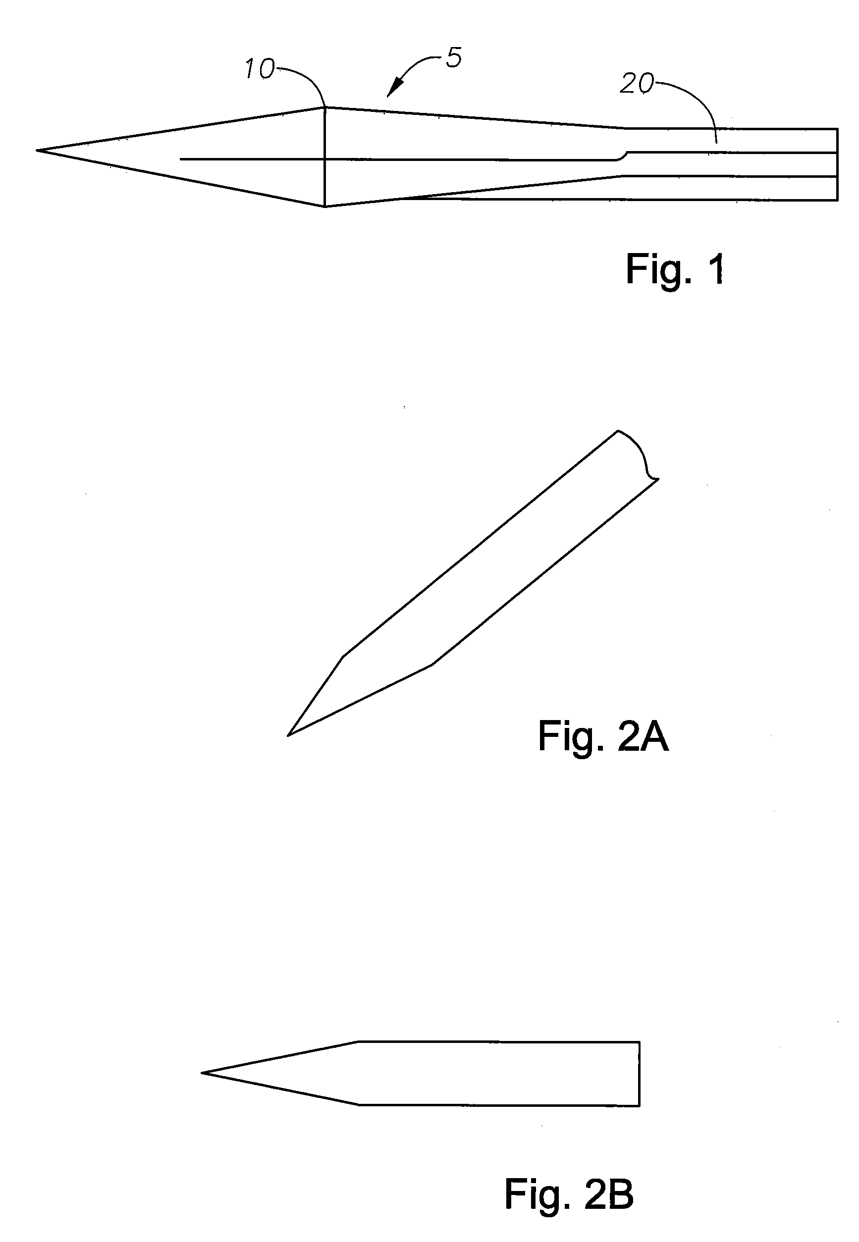
BACKGROUND OF THE INVENTION[0001]The present invention relates generally to incising tissue and in particular to micro-vitreoretinal trocar blades.[0002]Micro-vitreoretinal (MVR) blades are used to incise tissue for a trocar cannula. To minimize pulling, stretching, or tearing of tissue, the traditional approach of incising tissue for a trocar cannula has been to use an MVR trocar blade with an ear width that is larger than the trocar cannula inner lumen. FIG. 1 depicts a conventional MVR trocar blade, in which MVR trocar blade 5 has ears 10 with an associated width that is greater than the width of shaft 20. However, the design is constrained because of the way blade 5 must be ground, so, for example, there is a portion 15 of the blade 5 between the ears 10 and shaft 20 that does not cut tissue. FIGS. 2A and 2B depict views of a modified MVR trocar blade that can be inserted in the lumen of a trocar cannula. However, the short blade width reduces the width of an incision.[0003]Meth...

Claims


Application Information

Patent Timeline
IPC IPC(8): A61B17/34
CPCA61B17/3417A61F9/007A61B2017/3454A61B17/34A61B17/3209A61M25/01
Inventor AUCHTER, GREGORY A.AULD, JACK ROBERTBERARDI, RANDAL L.FALLER, HARRY E.HICKINGBOTHAM, DYSON W.MCCOLLAM, CHRISTOPHER L.SAFABASH, JASON H.SAUER, WILLARD L.
Owner ALCON RES LTD
Learn More