Silent solenoid valve for fluid regulation system

Inactive Publication Date: 2010-05-06
MAXITROL
View PDF21 Cites 20 Cited by
  • Summary
  • Abstract
  • Description
  • Claims
  • Application Information

AI Technical Summary

Benefits of technology

[0008]The present invention discloses a fluid regulator system. The system includes a housing. The housing defines an inlet for receiving a fluid, a passage in fluid communication with the inlet for accommodating the fluid, and an outlet in fluid communication with the passage for discharging the fluid. The system also includes a regulator for regulating flow of the fluid through the passage. At least one solenoid valve interrupts the flow of the fluid through the passage. The at least one solenoid valve includes a valve member disposed inline with the passage and movable between an open position and a closed position. A plunger having a top, a bottom, and a side wall extends between the top and the bottom. The bottom is operatively connected to the valve member for moving the valve member between the positions. A recess is defined in the top of the plunger. A solenoid is disposed around at least a portion of the plunger for actuating the plunger. A plunger stop is disposed adjacent the top of the plunger for stopping movement of the plunger when the valve member is in the open position. A plunger bumper assembly is disposed at least partially within the recess of the top of the plunger and at least partially between the top of the plunger and the plunger stop. The plunger bumper assembly includes a resilient component formed of a resilient material for dampening noise produced by a contact between the plunger bumper assembly and the plunger stop.

Problems solved by technology

Unfortunately, the striking of these two metallic surfaces against one another typically generates a “clicking” noise that most consumers find undesirable.

Method used


Image

  • Silent solenoid valve for fluid regulation system
  • Silent solenoid valve for fluid regulation system
  • Silent solenoid valve for fluid regulation system

Examples


second embodiment

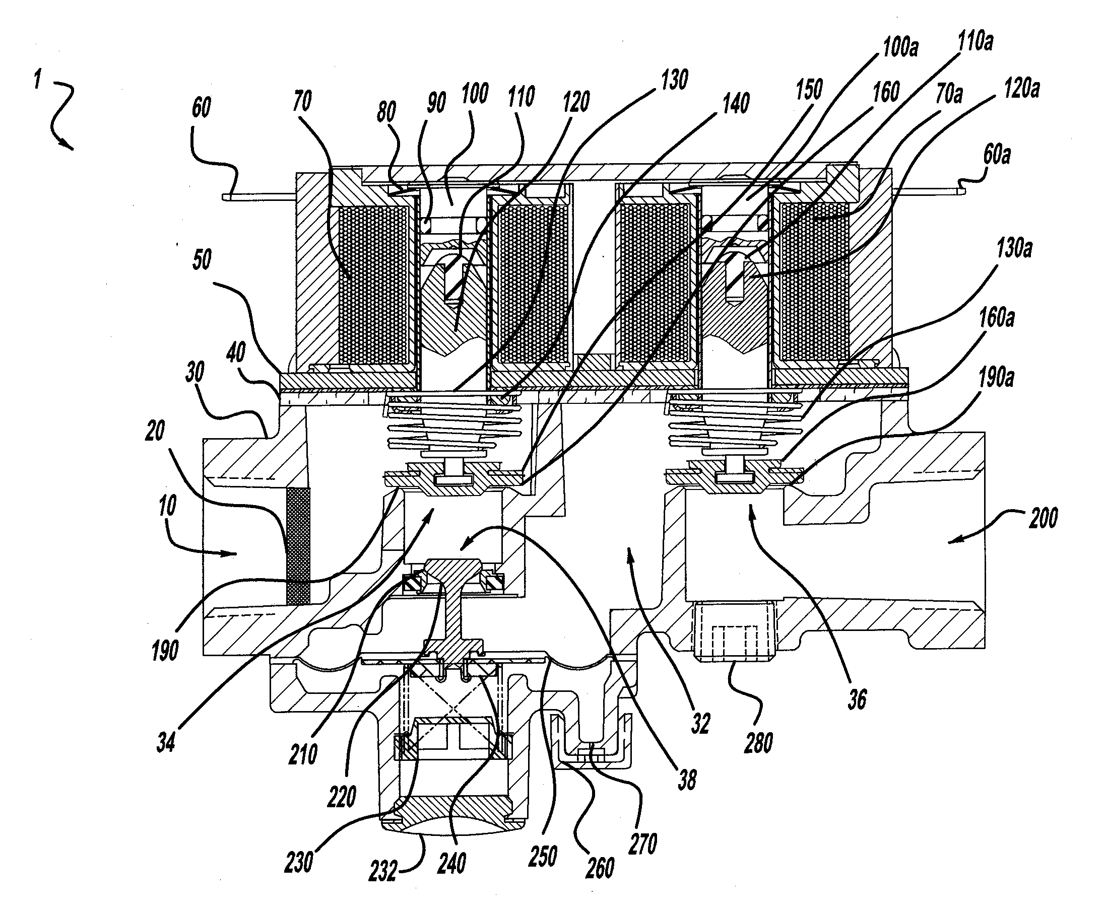
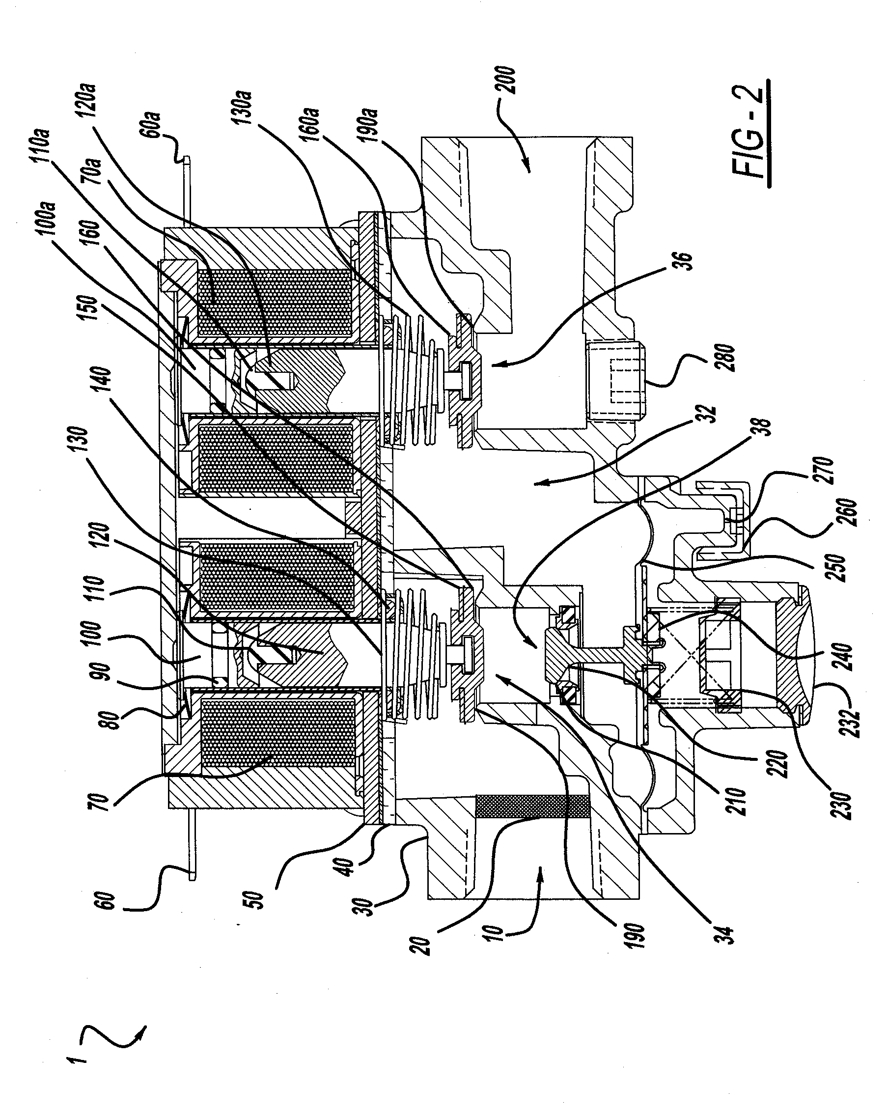
[0027]FIGS. 4 and 5 show a first embodiment of the plungers 120, 120a while FIGS. 6 and 7 show the plungers 120, 120a. Each plunger 120, 120a includes a top 312, a bottom 313, and a side wall 314 extending between the top 312 and the bottom 313. In these illustrated embodiments, the side wall 314 has a cylindrical shape. The top 312 and bottom 313 each have a frustoconical shape, as can be seen in FIGS. 7 and 9. That is, the top 312 and bottom 313 each have an angled portion (not numbered) extending inward away from the side wall 314 and a flat portion 316, wherein a diameter of the flat portion 316 is less than a diameter across the side wall 314.

[0028]The bottom 313 of each plunger 120, 120a is connected to the respective valve member 160, 160a, as can be seen in FIGS. 2 and 3. The plunger springs 130, 130a are also preferably connected to the bottom 313 of each respective plunger 120, 120a.

[0029]A recess 310 is defined by the top 312 of each plunger 120, 120a. More specifically,...

first embodiment

[0031]In the first embodiment, as shown in FIGS. 4 and 5, the plunger bumper assembly 300 includes a plunger recess part 302. The plunger recess part 302 includes a base portion 308 and a lip portion 306. The base portion 308 is disposed at least partially within the recess 310. As such, the base portion 308 has a cylindrical shape to cooperate with the cylindrical shape of the recess 310. The lip portion 306 extends generally perpendicularly away from the base portion 308 to define a ring shape. The lip portion 306 is separated from, i.e., does not make direct contact with, the top 312 of the plunger 120, 120a. The plunger recess part 302 is preferably formed of a metal, however, other materials, such as plastics, may be used, as is known to those skilled in the art. Regardless of the particular material chosen, the plunger recess part 302 should be durable, rigid, and if possible, non-magnetic. Said another way, the plunger recess part 302 may be non-resilient.

[0032]The resilient ...


PUM


Abstract

A fluid regulator system includes at least one solenoid valve for interrupting flow of the fluid. The solenoid valve solenoid valve includes a plunger that is actuated by a solenoid, i.e., a coil. A plunger stop limits movement of the plunger when the solenoid is energized. A recess defined a top of the plunger. A plunger bumper assembly is disposed at least partially within the recess of the top of the plunger and at least partially between the top of the plunger and the plunger stop. The plunger bumper assembly includes a resilient component formed of a resilient material for dampening noise produced by a contact between the plunger bumper assembly and the plunger stop.

Description

CROSS REFERENCE TO RELATED APPLICATION[0001]This application claims the benefit of provisional patent application No. 61 / 111,777, filed Nov. 6, 2008, which is hereby incorporated by reference.BACKGROUND OF THE INVENTION[0002]1. Field of the Invention[0003]The present invention relates generally to fluid regulators, and more specifically to gas regulators having solenoid valves.[0004]2. Description of the Related Art[0005]Gas regulators, including those having one and two-solenoid valve configurations (e.g., being connected in series fluid communication), have been used in various gas-fired appliances (e.g., gas fireplaces, space heaters, ovens, furnaces, water heaters, agricultural heaters, and so forth) for several years. These gas valves are typically operated electrically, and are generally incorporated into a regulator system that controls the flow of gas into the particular appliance.[0006]Typically, as shown in FIG. 1, these gas valves employ a plunger P housed in a solenoid s...

Claims


Application Information

Patent Timeline
IPC IPC(8): F16K31/02
CPCF16K31/0655F16K31/0696F23N2035/14F23N2035/18F23N2035/24F23N2235/14F23N2235/18F23N2235/24
Inventor PERZ, DANIEL J.SCHEUHER, JEFFREY
Owner MAXITROL
Why Eureka
Try Eureka