Method and apparatus for producing wind energy with reduced wind turbine noise

Inactive Publication Date: 2007-02-08
GENERAL ELECTRIC CO
View PDF7 Cites 79 Cited by
  • Summary
  • Abstract
  • Description
  • Claims
  • Application Information

AI Technical Summary

Benefits of technology

[0006] In one aspect, the present invention therefore provides a method for controlling noise from a wind park that includes a plurality of wind turbines. The method includes monitoring noise emission from the wind turbines in at least a near field area and utilizing a transfer function of noise emission to determine a noise impact importance of the wind turbines at one or more locations in a far field area beyond a boundary of the wind park. The method further includes determining which, if any, wind turbines to operate in a noise-reduced operation mode in accordance with the noise impact importance determination and controlling operation modes of the wind turbines in accordance with the determination of which, if any, wind turbines to operate in a noise reduced mode.
[0007] In another aspect, the present invention provides an apparatus for reducing noise impact from a wind park having a plurality of wind turbines. The apparatus includes at least one site reference microphone and a plurality of site boundary area microphones, and a computer configured to monitor noise emission from the wind turbines utilizing the site reference microphone(s) and the plurality of site boundary microphones. The computer is further configured to utilize a transfer function of noise emission to determine a noise impact importance of the wind turbines at one or more locations in the far field beyond a bounda

Problems solved by technology

However, this method may not necessarily lead to proper turbine noise reduction because wind turbine rotor noise exhibits sound directivity not necessarily maximum in down-wind direction.
Thus, wind direction statistics may not adequately address relevant noise contributions.
This method may

Method used


Image

  • Method and apparatus for producing wind energy with reduced wind turbine noise
  • Method and apparatus for producing wind energy with reduced wind turbine noise
  • Method and apparatus for producing wind energy with reduced wind turbine noise

Examples


Embodiment Construction

[0016] As used herein, “emission” with an “e” is a machinery or product noise generation that is attributed tot his machinery or product an can be measured in the near field area to determine the corresponding generated acoustic power (the measured quantity being the sound power level). “Immission” with an “I” is the far field area noise impact, often measured and qualified by noise map as a result of the combination of noise sources making noise in the far field with respect to any previous existing background noise map. Emission is thus a source term, while immission is the consequence of emission, i.e., the noise footprint or impact within the reception area. Also, as used herein, the terms “wind turbine park” and “wind park” are considered synonymous.

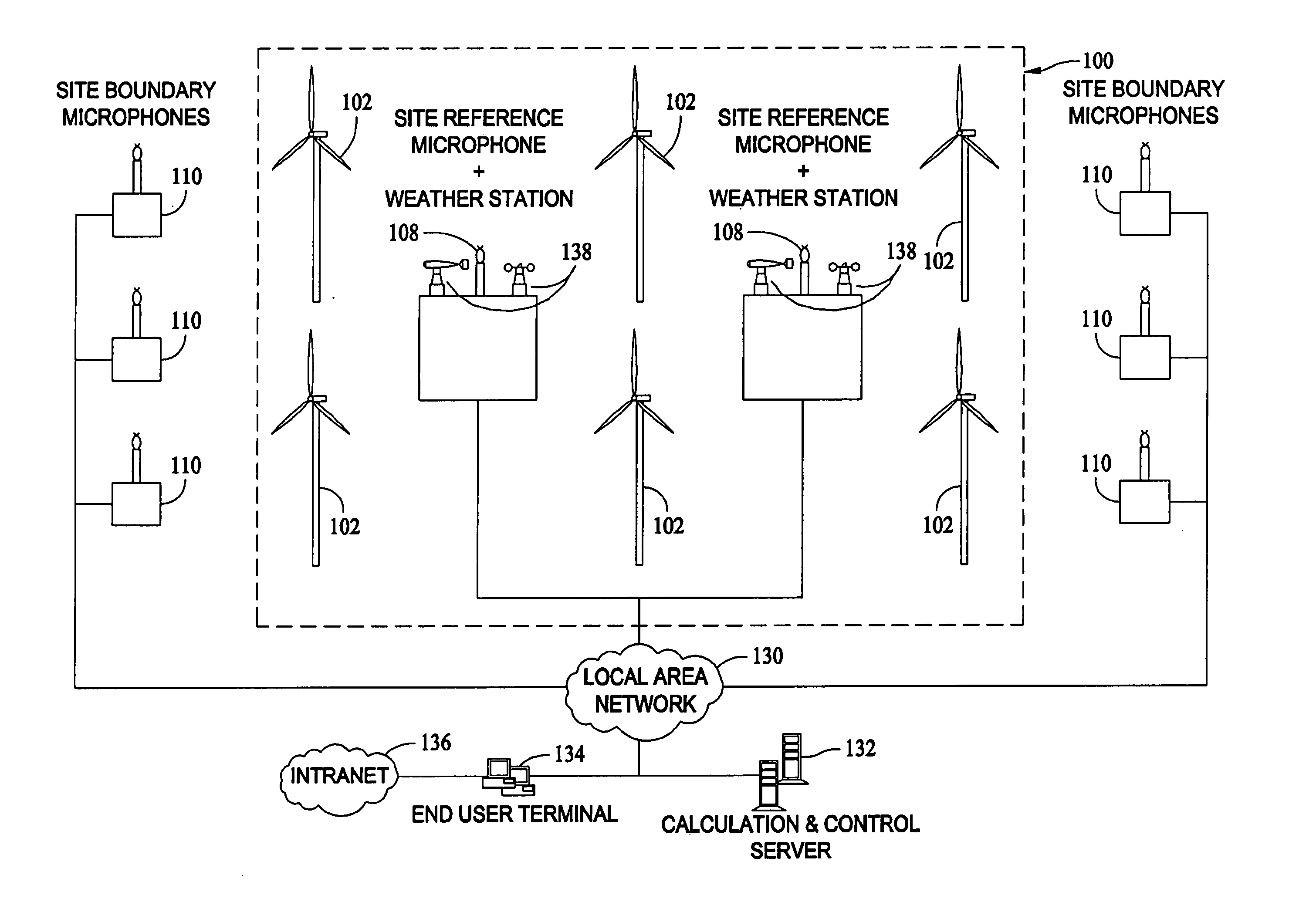
[0017] Technical effects of some configurations of the present invention include the reduction of noise impact produced by a wind park having a plurality of wind turbines, while enabling increased power production from the wind par...


PUM


Abstract

A method for controlling noise from a wind park that has a plurality of wind turbines includes monitoring noise emission from the wind turbines in at least a near field area and utilizing a transfer function of noise emission to determine a noise impact importance of the wind turbines at one or more locations in a far field area beyond a boundary of the wind park. The method further includes determining which, if any, wind turbines to operate in a noise-reduced operation mode in accordance with the noise impact importance determination and controlling operation modes of the wind turbines in accordance with the determination of which, if any, wind turbines to operate in a noise reduced mode.

Description

BACKGROUND OF THE INVENTION [0001] This invention relates generally to power generation systems and more particularly to methods and apparatus for reducing noise impact from wind turbine installations. [0002] In many parts of the world, the issuance of permits for wind turbine installations is based upon the environmental noise impact effected or potentially effected by the installation. For example, in most European countries, a maximum (fixed) sound pressure level is set by type of land area (agricultural, industrial, residential, or other) in the vicinity of wind turbine park boundaries, or in some noise regulation cases, the approach of industrial noise relative emergence is favored. Noise emergence is defined herein as the relative noise level increase related to an industrial installation with reference to the initial, existing background noise level. [0003] At least three known methods exist for controlling noise from wind turbine installations. In a first known method descri...

Claims


Application Information

Patent Timeline
IPC IPC(8): F04D27/02
CPCF05B2240/96F05B2260/96Y02E10/725Y02E10/723F03D7/048F05B2270/333F03D7/0296Y02E10/72
Inventor BONNET, LAURENT
Owner GENERAL ELECTRIC CO
Why Eureka
Try Eureka