[0026] By resetting or altering the reference
voltage of the amplifier during measurement, the present invention enables a
high gain amplifier to be used in obtaining measurements of an evoked neural response, thus enabling detection of smaller neural response signals than prior art measurement methods. While resetting the reference
voltage of the amplifier during measurement causes the output of the amplifier to represent the amplified sensed signal in piecewise fashion, the piecewise output signal segments can nevertheless be relatively easily reconstructed into a continuous waveform.
[0027] The step of altering the reference voltage of the
high gain amplifier is preferably performed by setting the reference voltage to be equal to a present value of the sensed signal. This can be simply achieved by a sample-and-hold circuit having an input from the sensed signal. In such embodiments, a present dc-offset of the sensed signal is essentially removed, such that the high
gain amplifier will only amplify and output variations of the sensed signal from the reference voltage. This enables such variations to be amplified by a relatively large amount, without the present dc-offset of the sensed signal and the slow variation of the signal causing the amplifier to enter saturation. It is to be appreciated that the present dc-offset is only “dc” when considered relative to the regularity with which the reference voltage of the high gain amplifier is altered.
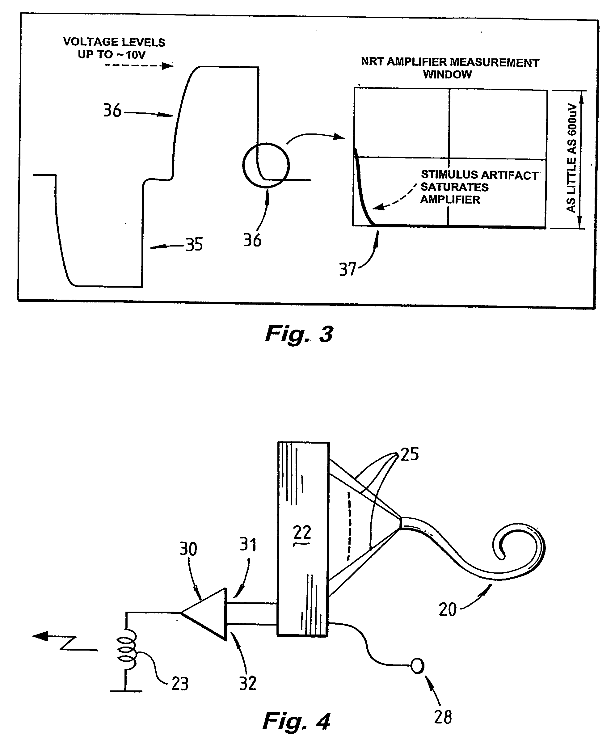
[0028] Preferably, at the commencement of every sample period, the reference voltage of the high gain amplifier is altered to be equal to the present value of the sensed signal. In such embodiments of the invention, every sample obtained at the output of the high gain amplifier represents a change in the sensed signal which has occurred since the previous sample. With a sufficiently high sample rate, the change in the sensed signal during the duration of the sample period will be relatively small, enabling a larger gain to be applied to the signal without saturating the amplifier. Thus, even where a relatively large stimulus artefact contributes to the sensed signal and would otherwise cause saturation of the amplifier, the present invention enables high gain amplification of the sensed signal while avoiding saturation of the amplifier caused by large stimulus artefacts. That is, the method of the present invention assists in common mode rejection. In such embodiments of the present invention the obtained samples can simply be integrated or summed to obtain a continuous waveform representing the amplified sensed signal.
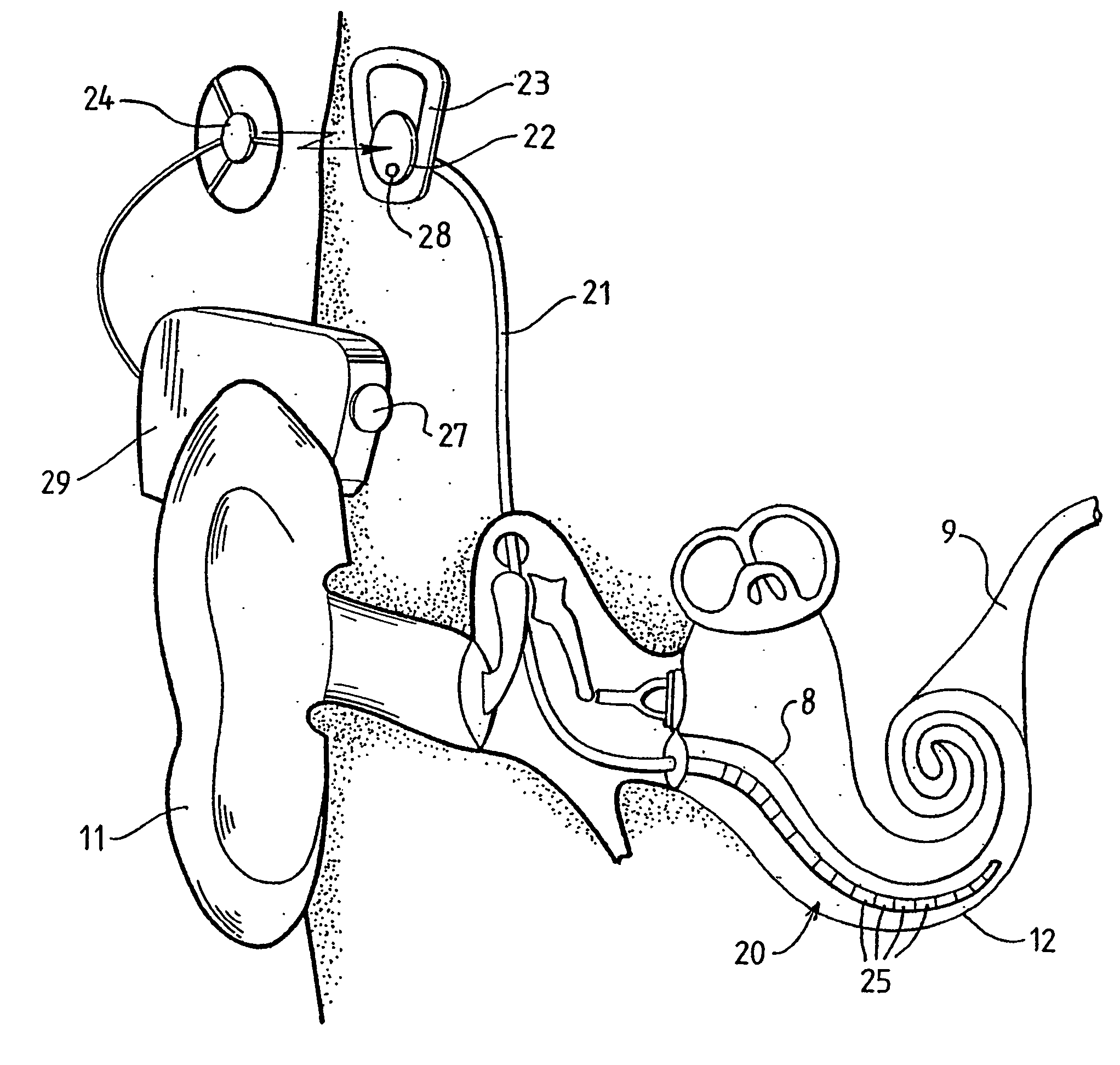
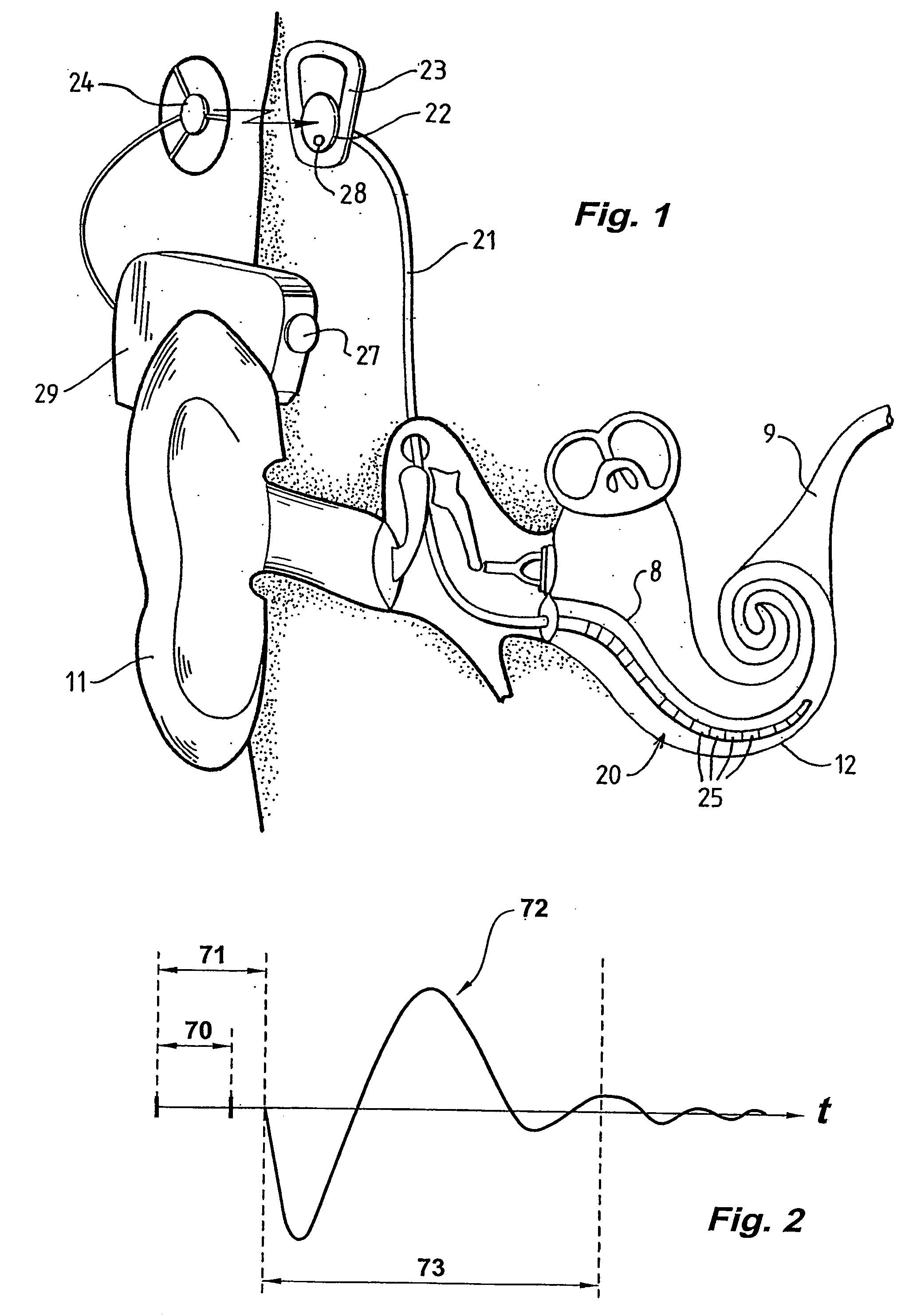
[0034] The device may comprise a
cochlear implant. In such embodiments the sensor may comprise one or more electrodes of an
electrode array of an implanted portion of the
cochlear implant. The
cochlear implant may be a totally implanted cochlear
implant, as described in PCT / AU01 / 00769 by the present applicant, the contents of which are incorporated herein by reference. While the present invention is advantageous when used in typical cochlear implants having a relatively simple implanted portion and an external processor, embodiments of the present invention in which the device is a totally implanted cochlear implant may be of particular
advantage, in that
processing of the sensed signal is performed prior to transmission of the obtained samples over a transcutaneous RF link, thus reducing the
impact of
noise of the RF link on the accuracy of the sampled data.
[0035] The present invention may be particularly advantageous when used in conjunction with stimulus artefact cancellation schemes. For example, the present invention, when combined with the artefact cancellation technique disclosed in International Application No. PCT / AU02 / 00500 by the present applicant, the contents of which are incorporated herein by reference, may enable particularly accurate
high resolution measurements of an evoked neural response to be obtained, despite the relatively
small amplitude of the neural response and the presence of stimulus artefacts of significantly larger amplitude. For example, embodiments of the present invention may obtain samples of the amplified sensed signal from the output of the high gain amplifier, and as each sample is obtained, transmit that sample across a transcutaneous RF link such that
processing of the samples can be performed externally. Alternatively, where the implanted portion has
processing capability, internal processing may be performed and may avoid the effects of
noise of the RF link on each sample.
[0043] means for setting a reference voltage at the reference input of the high gain amplifier equal to a present value of the sensed signal in order to prevent the high gain amplifier saturating with variations of the sensed signal.

