Wind turbine noise control methods

Inactive Publication Date: 2014-09-04
VESTAS WIND SYST AS
View PDF13 Cites 12 Cited by
  • Summary
  • Abstract
  • Description
  • Claims
  • Application Information

AI Technical Summary

Benefits of technology

[0008]According to a first aspect of the invention there is provided a method of operating a wind turbine comprising at least one trailing edge control surface on at least one rotor blade, comprising operating the wind turbine in a first mode, in which a rotor blade angle of attack and a trailing edge control surface deflection are set according to one or more wind turbine control parameters, and sel

Problems solved by technology

Wind turbines can emit noise, with aerodynamic noise sources including separated/stall flow noise, trailing edge noise (blunt and otherwise), laminar boundary layer vortex shedding noise, tip noise, noise from surface imperfections (such as sensors, damage, unwanted adhesions), blade rotation noise, lifting/control surface loading noise, noise from the interaction between the blades and the wake vortex (unsteady loading noise), noise from the interaction of the blades with atmospheric tu

Method used


Image

  • Wind turbine noise control methods
  • Wind turbine noise control methods
  • Wind turbine noise control methods

Examples


Example

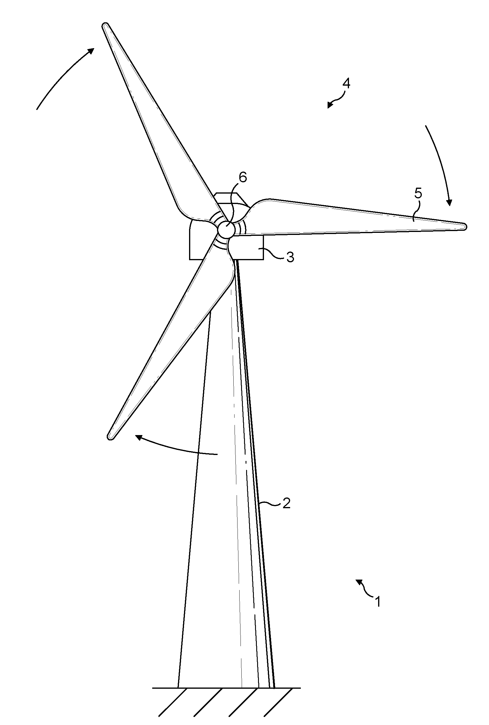
[0031]An embodiment of the invention relates to a wind turbine having a rotor with one or more blades, wherein one or more of the blades includes at least one control surface.

[0032]The term control surface refers to a movable surface of the wind turbine blade for modifying the aerodynamic profile of the wind turbine blade. Examples of control surfaces include ailerons, leading or trailing edge flaps, leading edge slats, Krueger flaps, Gurney flaps (wickerbill flaps), stall inducing flaps, vortex generators for controlling the boundary layer separation, adaptive elastic members incorporated in the blade surface, means for changing the surface roughness, adjustable openings or apertures, or movable tabs. A blade may have one or more such control surfaces, and each control surface will typically only extend along part of the spanwise length of a blade.

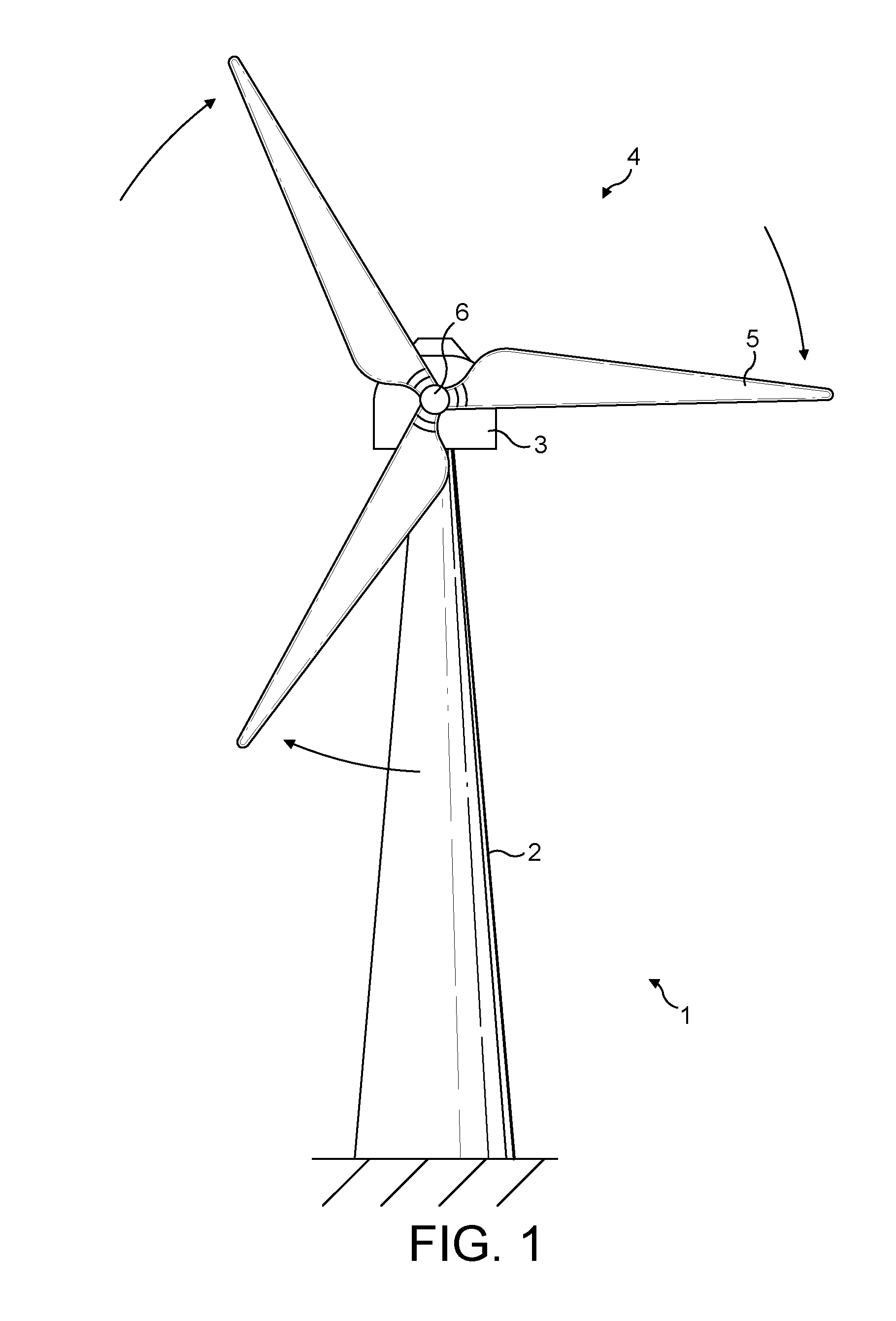
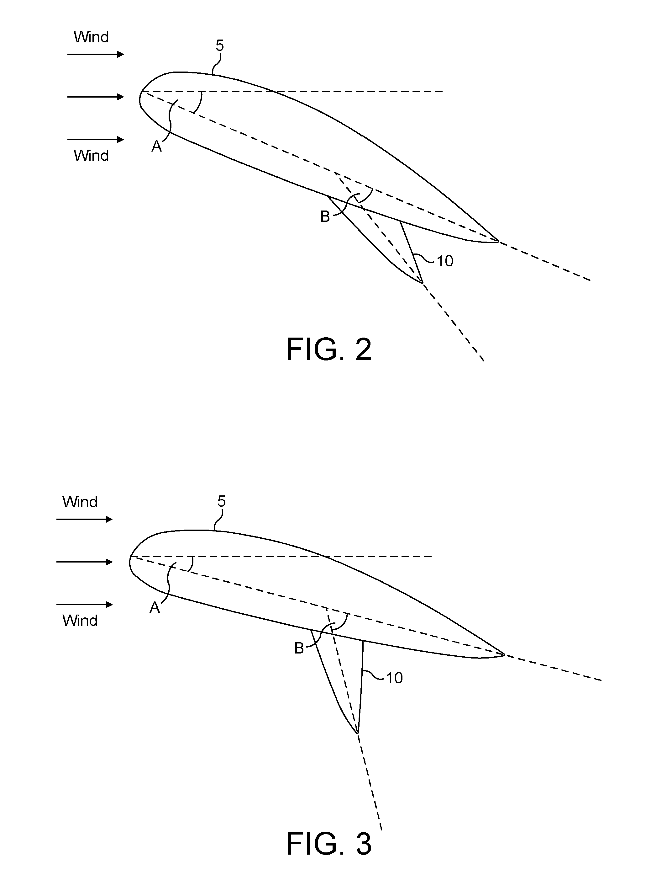
[0033]FIG. 2 shows a wind turbine rotor blade 5 in a first operating mode. Blade 5 describes an angle of attack A to the direction of th...


PUM


Abstract

A wind turbine having at least one trailing edge control surface (10) on at least one rotor blade (5) is operated in a first mode, in which a rotor blade angle of attack and a trailing edge control surface deflection are set according to one or more wind turbine control parameters. The turbine is selectively operated in a second, noise reduced, mode, in which for a given set of wind turbine control parameters, the trailing edge control surface deflection is increased towards the pressure side and the rotor blade angle of attack is decreased with respect to the first mode. In the second mode, for a given set of control parameters, the loading on the blade (5) is on average closer to a hub than in the first operating mode.

Description

TECHNICAL FIELD[0001]This invention relates to wind turbines generally, and specifically to the control of noise emitted by wind turbines.BACKGROUND OF THE INVENTION[0002]FIG. 1 illustrates a conventional wind turbine 1. The wind turbine 1 comprises a wind turbine tower 2 on which a nacelle 3 is mounted. A rotor 4 comprising at least one blade 5 is mounted on a hub 6. The hub 6 is connected to the nacelle 3 through a low speed shaft (not shown) extending from the nacelle front. The wind turbine illustrated in FIG. 1 may be a small model intended for domestic or light utility usage, or may be a large model, such as those that are capable of generating several MWs of power and are suitable for use in large scale electricity generation on a wind farm for example. In the latter case, the diameter of the rotor could be as large as 150 metres or more.[0003]Most modern wind turbines are controlled and regulated continuously during operation with the purpose of ensuring optimal performance ...

Claims


Application Information

Patent Timeline
IPC IPC(8): F03D7/02
CPCF03D7/0296F03D7/0232F05B2270/333Y02E10/72
Inventor ABDALLAH, IMADGODSK, KRISTIAN BALSCHMIDTROMBLAD, JONASLIM, CHEE KANG
Owner VESTAS WIND SYST AS
Why Eureka
Try Eureka