Method of setting mold clamping force of injection molding machine

a technology of injection molding machine and clamping force, which is applied in the direction of auxillary shaping apparatus, manufacturing tools, ceramic shaping apparatus, etc., can solve the problems of unnecessarily increasing consumption energy, reducing the accuracy of mold clamping force, so as to facilitate the setting of proper mold clamping force. more accurate and stable

Active Publication Date: 2010-05-06
NISSEI PLASTIC IND CO LTD
View PDF7 Cites 11 Cited by
  • Summary
  • Abstract
  • Description
  • Claims
  • Application Information

AI Technical Summary

Benefits of technology

[0016](7) According to another preferred aspect, the detection signal Dxn obtained from the mold position sensor 4 is filtered by the filter processing portion 5 to remove noise, and thus it is p

Problems solved by technology

In this type of mold clamping device, for example, a high-pressure mold clamping is performed at the maximum mold clamping force of the mold clamping device to achieve secure clamping without the occurrence of or the like; however, since an excessive mold clamping force is applied to the m

Method used


Image

  • Method of setting mold clamping force of injection molding machine
  • Method of setting mold clamping force of injection molding machine
  • Method of setting mold clamping force of injection molding machine

Examples


Embodiment Construction

[0025]The present invention will now be described in detail, using a preferred embodiment of the present invention, based on the accompanying drawings. The accompanying drawings are not used for specifying the present invention but are used to make the invention easily understood. The detailed description of known parts will be omitted so as not to make the invention unclear.

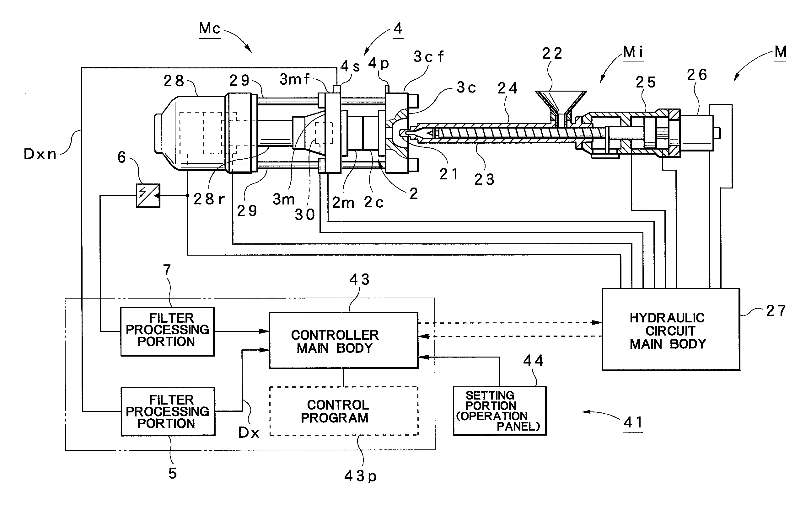
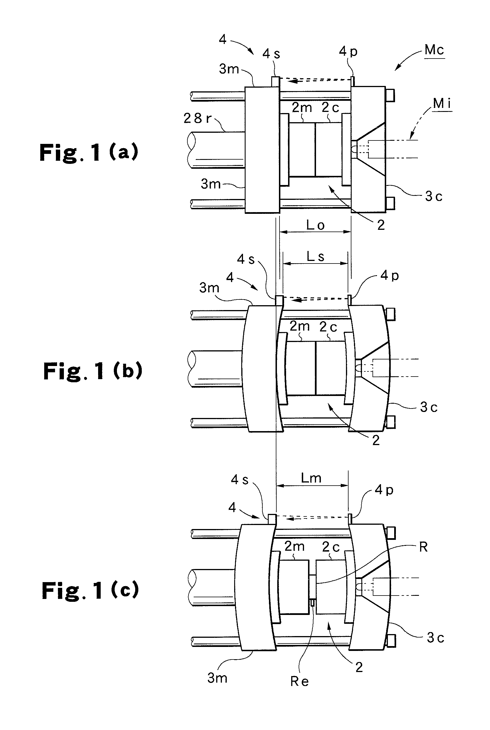
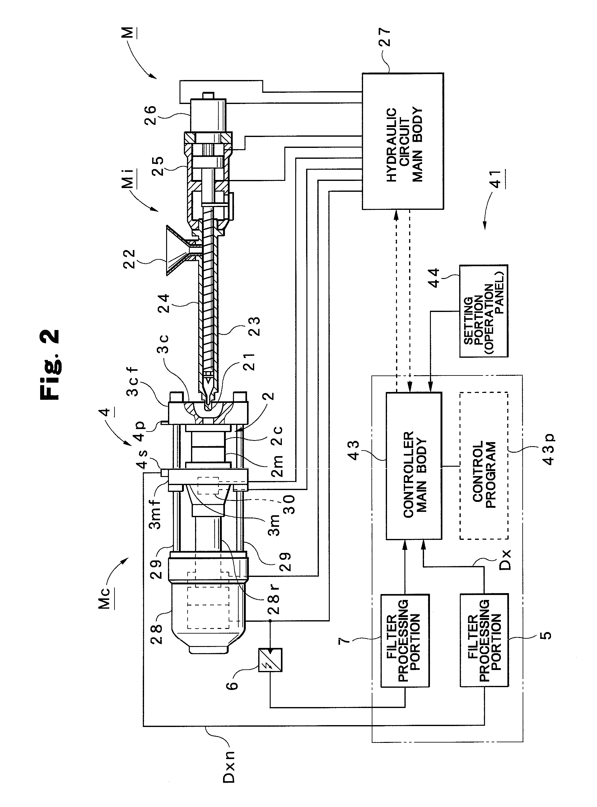
[0026]The configuration of an injection molding machine M that can perform a method of setting a mold clamping force according to this embodiment will first be described with reference to FIGS. 1 and 2.

[0027]In FIG. 2, the reference numeral M represents an injection molding machine, and it is provided with an injection device Mi and a mold clamping device Mc. The injection device Mi is provided with a heating cylinder 23 that has an injection nozzle 21 at the front end and a hopper 22 for material supply at the rear portion; the heating cylinder 23 incorporates a screw 24. At the rear portion of the heating cyli...


PUM

PropertyMeasurementUnit
Lengthaaaaaaaaaa
Lengthaaaaaaaaaa
Fractionaaaaaaaaaa

Abstract

Test molding is performed by sequentially clamping a mold 2 with a mold clamping force (100%, 80%, 70%, . . . ) obtained by sequentially lowering a mold clamping force by a predetermined amount from the maximum mold clamping force (100%); with mold position sensors 4 provided on outer surfaces 3cf and 3mf of a fixed platen 3c supporting a fixed mold 2c of the mold 2 and a movable platen 3m supporting a movable mold 2m of the mold 2, a relative position (mold position Xc) of the movable platen 3m with respect to the fixed platen 3c in an injection process is detected; and, when at least a variation that meets predetermined conditions is produced on the mold position Xc, a mold clamping force obtained by increasing a mold clamping force at a time of occurrence of the variation by a predetermined amount is set as a proper mold clamping force Fs.

Description

TECHNICAL FIELD[0001]The present invention relates to a method of setting a mold clamping force of an injection molding machine, and such a method is suitably used to set a mold clamping force smaller than the maximum mold clamping force when a mold is clamped by a mold clamping device.BACKGROUND ART[0002]An injection molding machine is generally provided with a mold clamping device for clamping a mold. In this type of mold clamping device, for example, a high-pressure mold clamping is performed at the maximum mold clamping force of the mold clamping device to achieve secure clamping without the occurrence of or the like; however, since an excessive mold clamping force is applied to the mold, the mold is degraded earlier and consumption energy is unnecessarily increased, and stains, such as weld marks, burns and black streaks, and damages on the surface of cavities are produced due to insufficient gas removal, with the result that it is necessary to perform repair process. Thus, if ...

Claims


Application Information

Patent Timeline
IPC IPC(8): B29C45/80
CPCB29C45/7653B29C2945/76083B29C2945/76227B29C2945/76387B29C2945/76498B29C2945/76702
Inventor KUDO, YOSHIAKIHAKODA, TAKASHINAKAMURA, KIYOSHIMOROZUMI, SUSUMU
Owner NISSEI PLASTIC IND CO LTD
Why Eureka
Try Eureka