Automotive Construction Engine and Lifting Column for a Contruction Engine

a construction engine and engine technology, applied in the field of construction engines, can solve the problems of not being able to adjust any other operating positions in a flexible manner, and losing information about the position of the machin

Active Publication Date: 2010-05-06
WIRTGEN AMERICA
View PDF13 Cites 31 Cited by
  • Summary
  • Abstract
  • Description
  • Claims
  • Application Information

AI Technical Summary

Problems solved by technology

When the piston has left the pre-defined sensor positions, the information about the position of the machine is lost.
It is, in particular, not possible to adjust any other operating positions in a flexible manner without remounting the position sensors.
It is not even possible to, for instance, adjust an operating position that is parallel to the pre-adjusted operating position but deviates from the same in height.
What is more, it is not possible to adjust a defined transverse inclination or any other practical position of the machine frame or the machine respectively without cumbersome remounting efforts.
This creates the additional problem that the machine frame can adopt a different distance to the ground surface or traffic surface because of different loads or load distributions whi

Method used


Image

  • Automotive Construction Engine and Lifting Column for a Contruction Engine
  • Automotive Construction Engine and Lifting Column for a Contruction Engine
  • Automotive Construction Engine and Lifting Column for a Contruction Engine

Examples


Embodiment Construction

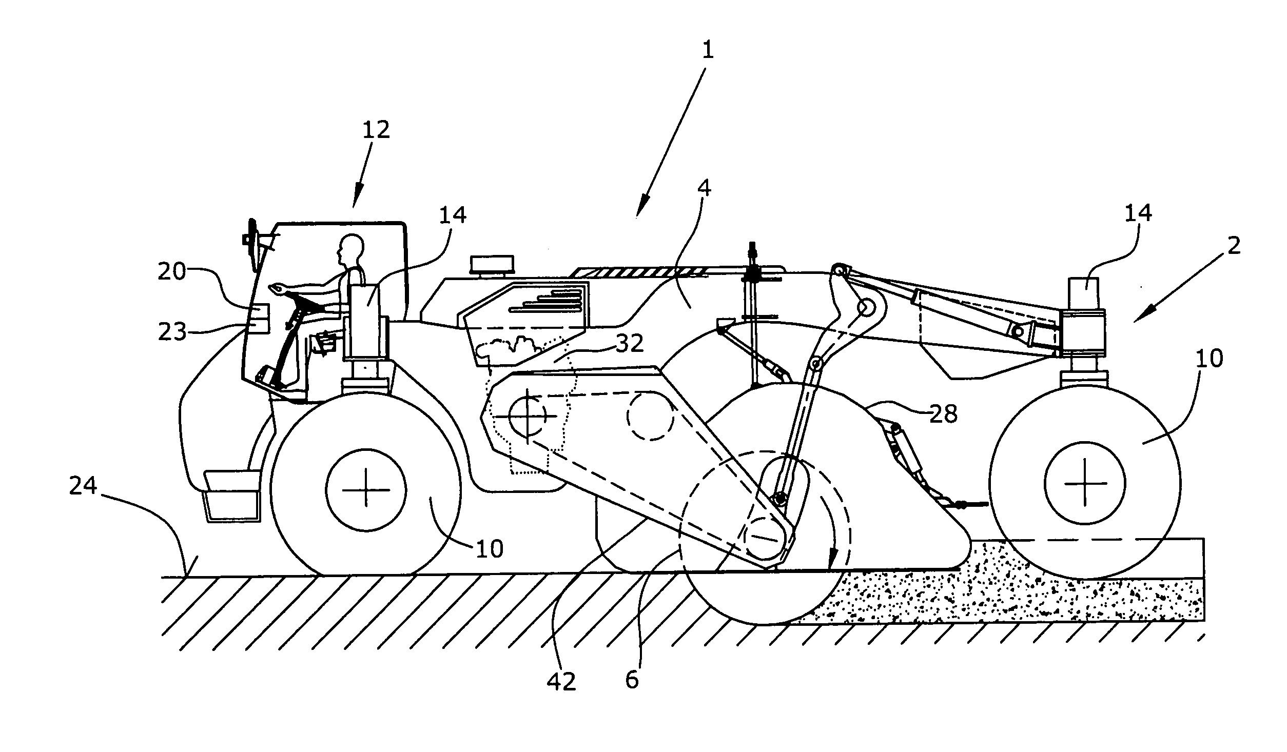
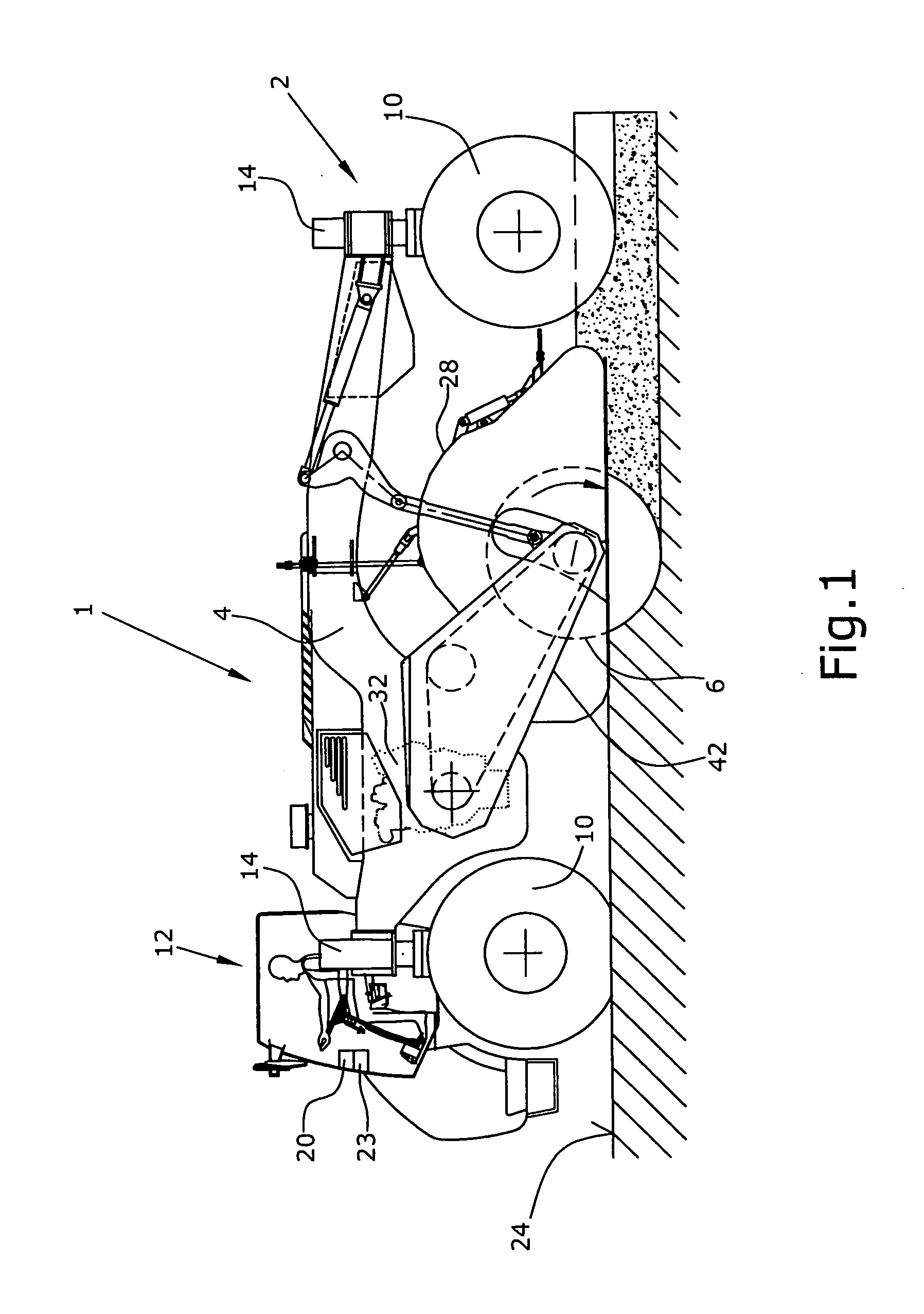
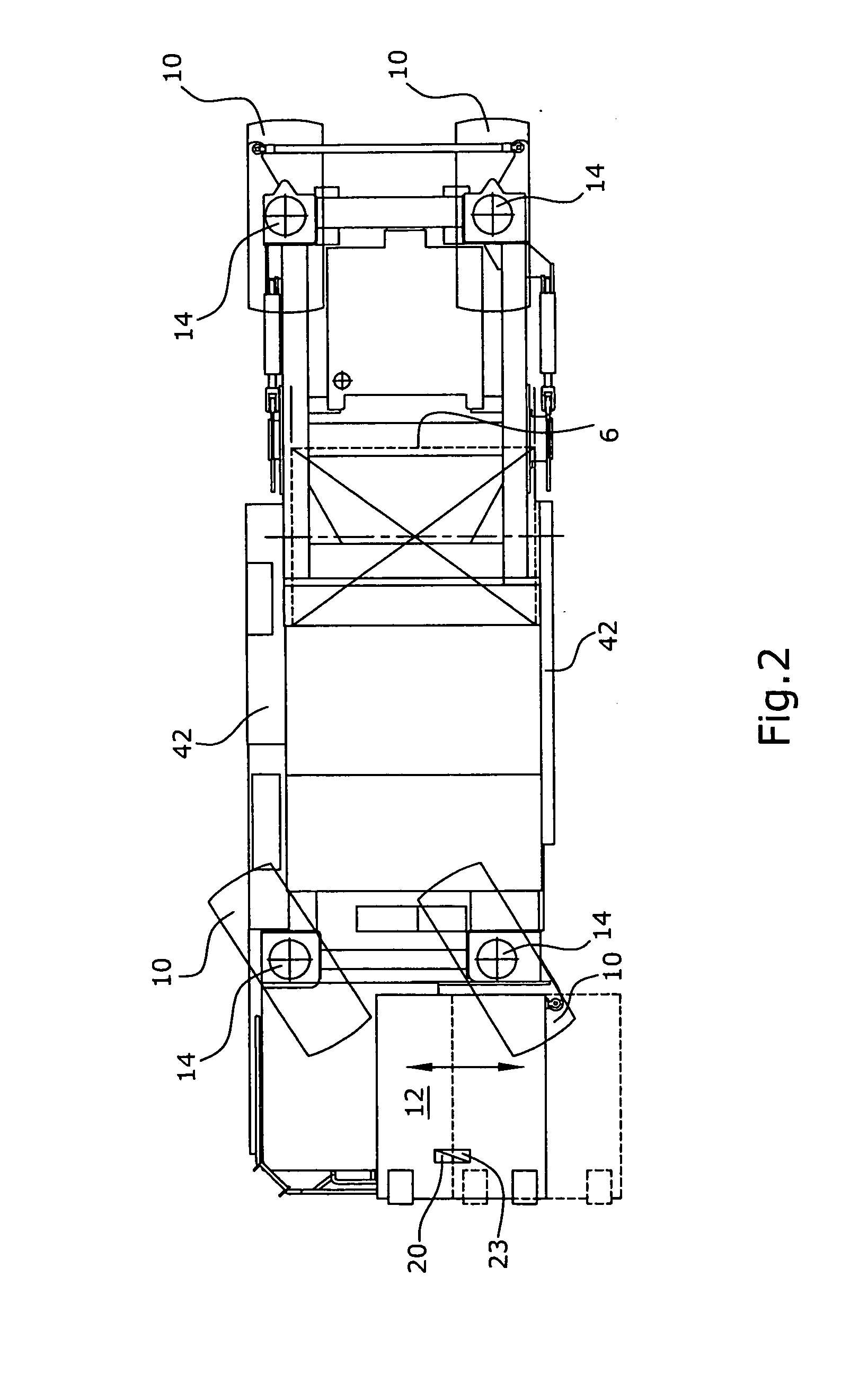
[0039]FIG. 1 shows a road construction machine 1 for producing and working carriageways by stabilizing insufficiently stable soils or by recycling road surfaces, with a machine frame 4 supported by a chassis 2, as it is basically known from DE 103 57 074 B3. The chassis 2 is provided with two each rear and front wheels 10, which are attached to lifting columns 14 in a height-adjustable manner and can be raised and lowered independently of one another or also synchronously to one another. It is understood that other drive means like, for instance, crawler track units may also be provided in lieu of the wheels 10. The lifting columns 14 are attached to the machine frame 4.

[0040]Both axles of the chassis, which are formed by the front and rear wheels 10 respectively, may be steerable.

[0041]As can be seen from FIGS. 1 and 2, an operator's platform 12 for a vehicle driver is arranged at the machine frame 4 above the front wheels 10 or in front of the front wheels 10, with a combustion en...


PUM


Abstract

Disclosed is an automotive road construction engine (1), particularly a recycler or a cold stripping machine, comprising an engine frame (4) that is supported by a chassis (2), a working roller (6) which is stationarily or pivotally mounted on the engine frame (4) and is used for machining a ground surface or road surface (24). The chassis (2) is provided with wheels (10) or tracked running gears which are connected to the engine frame (4) via lifting column (14) and are vertically adjustable relative to the engine frame (4). The lifting columns (14) are composed of two hollow cylinders (13, 15) that can be inserted into each other, are used as a guiding unit, and preferably coaxially accommodate at least one piston-cylinder unit (16) therein for vertical adjustment purposes. Each individually vertically adjustable lifting column (14) is equipped with a device (18) for measuring the actual vertical state of the lifting column (14). Said measuring device (18) is coupled to lifting column (14) elements that can be adjusted relative to each other according to the vertical position in such a way that the measuring device (18) can continuously detect a path signal regarding the vertical position of each lifting column (14). A controller (23) which receives the measured path signals of the measuring devices (18) of all lifting columns (14) regulates the vertical state of the lifting columns (14) in accordance with the measured path signals of the measuring devices (18) and/or the changes thereof over time.

Description

BACKGROUND OF THE INVENTION[0001]The invention relates to an automotive construction machine in accordance with the pre-characterizing clause of claim 1, as well as a lifting column for a construction machine in accordance with the pre-characterizing clause of claim 18.[0002]Such construction machinery is known, for instance, from DE 103 57 074 B3. The said construction machine shows a machine frame that is supported by a chassis, as well as a working drum that is mounted at the machine frame in an immovable and / or pivotable manner, and is used for working a ground surface or traffic surface. The chassis is provided with wheels and / or crawler track units which are connected to the machine frame via lifting columns and are individually adjustable in height relative to the machine frame.[0003]The adjustment in height is made possible by a controller that raises or lowers the lifting columns by controlling the hydraulic input or hydraulic discharge of piston cylinder units in the lifti...

Claims


Application Information

Patent Timeline
IPC IPC(8): E01C23/00E01C23/088G06F19/00B62D24/04B60G17/00B60G3/01
CPCB60G3/01B60G17/019B60G2204/421E01C21/00B60G17/015E01C23/127E01C23/088B60G2300/09
Inventor BUSLEY, PETERTEWES, GUNTER
Owner WIRTGEN AMERICA
Why Eureka
Try Eureka