
Device for Determining the Position of at Least One Structure on an Object, Use of an Illumination Apparatus with the Device and Use of Protective Gas with the Device

a technology for determining the position of a structure and an object, which is applied in the direction of optical devices, measurement devices, instruments, etc., to achieve the effect of being convenient and economically availabl

Active Publication Date: 2010-05-06
KLA TENCOR MIE
View PDF55 Cites 4 Cited by
  • Summary
  • Abstract
  • Description
  • Claims
  • Application Information

AI Technical Summary

Benefits of technology

[0034] A further advantage of the invention is the use of protective gas in a device for determining the position of at least one structure on an object. At least one optical component in the path of the light from at least one illumination apparatus to at least one optical element is surrounded by protective gas.
[0035] It is particularly advantageous if all the optical components in the path of the light from the at least one illumination apparatus to the optical elements are surrounded by protective gas. For this purpose, the optical components are surrounded by an encapsulation and the light from the at least one illumination apparatus passes within the encapsulation. The protective gas in the encapsulation is nitrogen, since it is particularly readily and economically available.
[0036] Further advantageous embodiments and uses of the invention are contained in the subclaims.

Problems solved by technology

In addition, the range within which the object to be measured is moved must not be influenced by heat production from possibly suitable illumination apparatus.

Method used


Image

  • Device for Determining the Position of at Least One Structure on an Object, Use of an Illumination Apparatus with the Device and Use of Protective Gas with the Device
  • Device for Determining the Position of at Least One Structure on an Object, Use of an Illumination Apparatus with the Device and Use of Protective Gas with the Device
  • Device for Determining the Position of at Least One Structure on an Object, Use of an Illumination Apparatus with the Device and Use of Protective Gas with the Device

Examples


Embodiment Construction

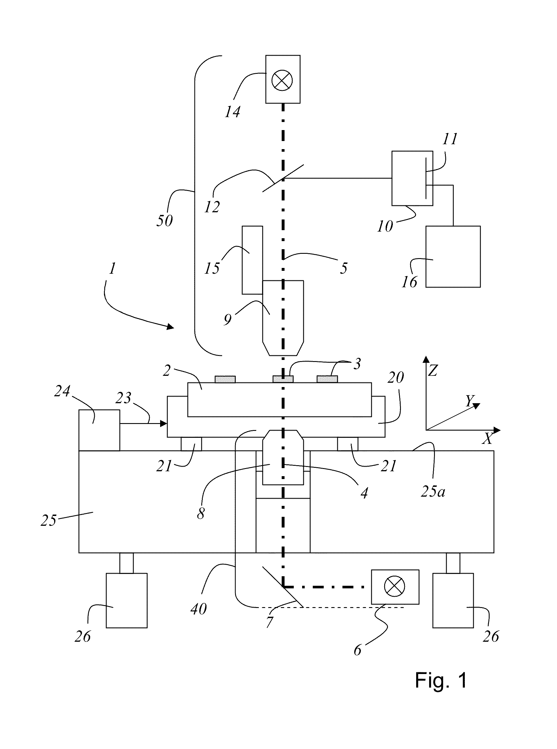
[0057]FIG. 1 shows a schematic representation of a coordinate measuring machine as has long been known from the prior art. The coordinate measuring machine is identified in the further description as a device. It should also be noted that in the description below and in the drawings, the same elements are identified with the same reference signs.

[0058] A device is used, for example, for determining the width (CD-critical dimension) of a structure on a substrate 2. Also, using the device, the position of a structure 3 on the substrate can be determined. Although the device shown in FIG. 1 has long been known from the prior art, for the sake of completeness, the operation of the device and the arrangement of the individual elements of the device will be discussed.

[0059] The device 1 comprises a measuring table 20, which is arranged displaceable on air bearings 21 in a plane 25a, in the X-coordinate direction and in the Y-coordinate direction. For the mounting of the measuring table ...


PUM


Abstract

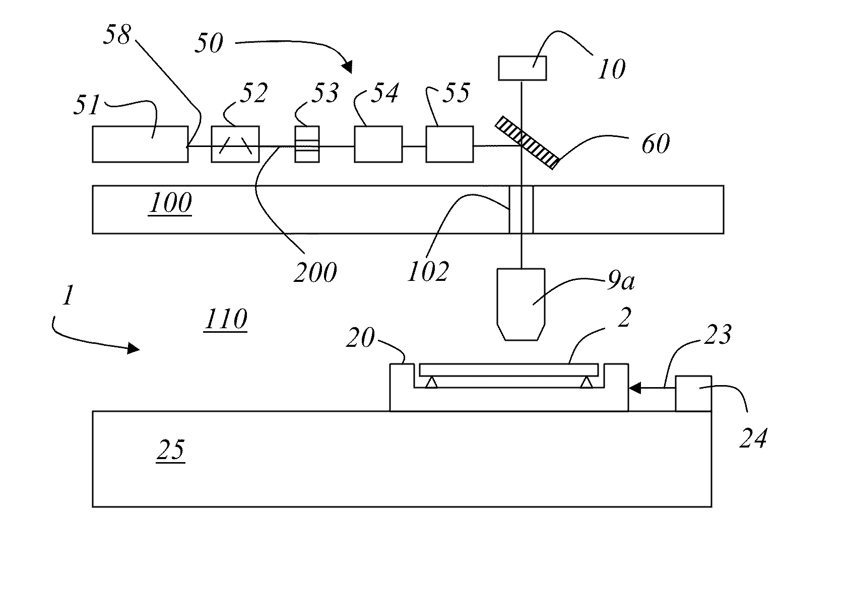
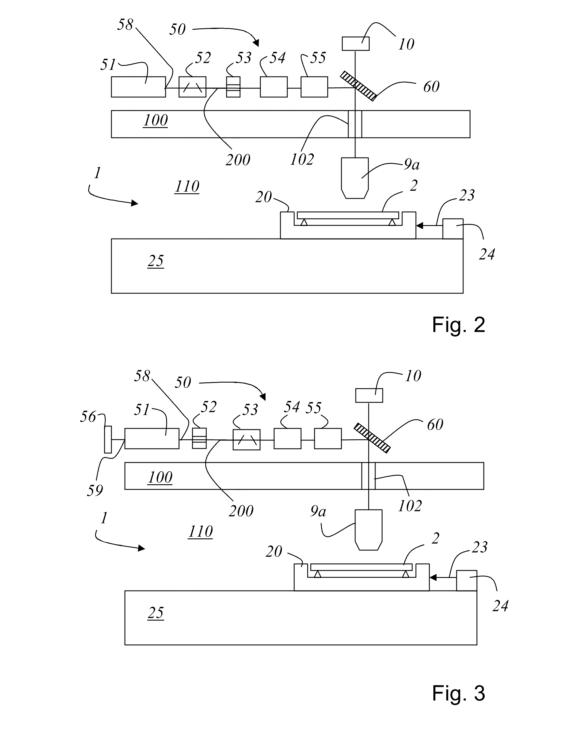
A device for determining the position of a structure (3) on an object (2) in relation to a coordinate system is disclosed. The object (2) is placed on a measuring table (20) which is movable in one plane (25a), wherein a block (25) defines the plane (25a). At least one optical arrangement (40, 50) is provided for transmitted light illumination and / or reflected light illumination. The optical arrangement (40, 50) comprises an illumination apparatus (41, 51) for reflected light illumination and / or transmitted light illumination and at least one first or second optical element (9a, 9b), wherein at least part of the at least one optical element (9a, 9b) extends into the space (110) between the block (25) and an optical system support (100). The block (25) and / or the optical system support (100) separates the illumination apparatus (41, 51) spatially from the plane (25a) in which the measuring table (20) is movable.

Description

RELATED APPLICATIONS [0001] This application claims priority to German Patent Application No. 10 2007 007 660.8 filed on Feb. 13, 2007, and German Patent Application No. 10 2007 049 133.8, filed on Oct. 11, 2007, and claims the benefit under 35 USC 119(e) of U.S. Provisional Application No. 60 / 889,595, filed on Feb. 13, 2007, all of which are incorporated herein by reference in their entirety.BACKGROUND OF THE INVENTION [0002] The present invention relates to a device for determining the position of a structure on an object. In particular, the invention relates to a device for determining the position of a structure on an object in relation to a coordinate system. The object is placed on a measuring table which is movable in one plane, wherein a block defines a plane in which the measuring table is movable. At least one laser interferometer for determining a positional displacement of the measuring table in the plane is further provided. At least one optical arrangement is provided ...

Claims


Application Information

Patent Timeline
Patent Type & Authority Applications(United States)
IPC IPC(8): G01B11/14
CPCG01B11/002G03F1/84G03F7/70625G01B9/02012G01B9/02027G01B9/02082
Inventor HEIDEN, MICHAEL
Owner KLA TENCOR MIE
Learn More