
Combination Storage, Dispensing and Feeding Device for Domestic Animals

a technology for domestic animals and storage, applied in the field of food bowls, can solve the problems of depriving animals of dietary variety, nutrition, or both, and failing to provide adequate means for retaining elements, etc., and achieves the effects of reducing the risk of mechanical failure, and reducing the cost of operation

Inactive Publication Date: 2014-12-04
FAIRBANKS PUTNAM R
View PDF12 Cites 20 Cited by
  • Summary
  • Abstract
  • Description
  • Claims
  • Application Information

AI Technical Summary

Benefits of technology

The present invention provides a new net feeding device that is cost-effective, convenient, simple, and user-friendly. It requires minimal effort and dexterity to operate. The design eliminates moving parts, reducing the risk of breakage or malfunctions due to wear or improper usage. This increases reliability and longevity of the device.

Problems solved by technology

Traditionally pet owners and other keepers of animals have been faced with the problem of regularly maintaining the sanitation of dishes, plates and bowls in which they serve food for their domestic animals.
Unfortunately these products deprive the animals of dietary variety, nutrition, or both.
While that seems useful, a major latent flaw in this design is that it fails to provide adequate means for its retaining elements to successfully retain a stack of inserts that is always changing in height every time a used liner is discarded.
The same clamps and anti-spin prongs that retain a large number of inserts in position will not be equally successful in retaining a single insert in position without added provisions.
As will be seen, this design is vastly more complicated than it needs to be, and vastly more complicated than the device disclosed by the present patent application.
Complexity adds increased manufacturing burden and prohibitive costs.
Another liability of this device is the added complication, dexterity, and effort required of user in having to mechanically disengage and then engage retaining element each and every time a liner needs to be disposed of.
Still another fault of this device is that the uppermost edges of all the inserts lay atop and outside of the outer dish, and will always be susceptible of food spillage and contamination from previous feedings.
That raises serious sanitation and aesthetic concerns.
That means that the success or failure of his device will always be subject to the design and configuration of presently available liners and the whim of those who supply them.
Unfortunately that limitation precludes all kinds of possible other designs imagined by the manufacturer of the device proposed in the present patent application.
While the introduction of a spring loaded base suggests an advancement on the prior art, it falls short.
As with the previously discussed patent, the externally added hinge, latch and retaining ring all add needless complexity and cost to the manufacturing, marketing, mass acceptance and even use of this invention.
Again, the same need to then reposition rim and re-engage lock is wearisome and adds needless dexterity and effort to the use of the device.
The insistence upon a spring of uniform pitch from base to its top in order to support inserts again adds more engineering and manufacturing complexity, as well as needless costs.
Still another flaw, the inclusion of a permanent bowl within the outer bowl, to be used as a necessary means to keep disposable inserts horizontally aligned to the outer retaining base, is another claim that makes no engineering, commercial or practical sense.
It only hurts the viability of the product.
Not only that it fails by its own design.
As inserts are used and discarded, and as the spring loaded permanent bowl begins to arise accordingly, the tapered match between the permanent bowl and the retaining base is totally lost.
Along with it, the lateral stability between the permanent bowl with inserts, and the retaining base envisioned by the inventor, is equally lost.
This only adds more manufacturing complexity and cost.

Method used


Image

  • Combination Storage, Dispensing and Feeding Device for Domestic Animals
  • Combination Storage, Dispensing and Feeding Device for Domestic Animals
  • Combination Storage, Dispensing and Feeding Device for Domestic Animals

Examples


Embodiment Construction

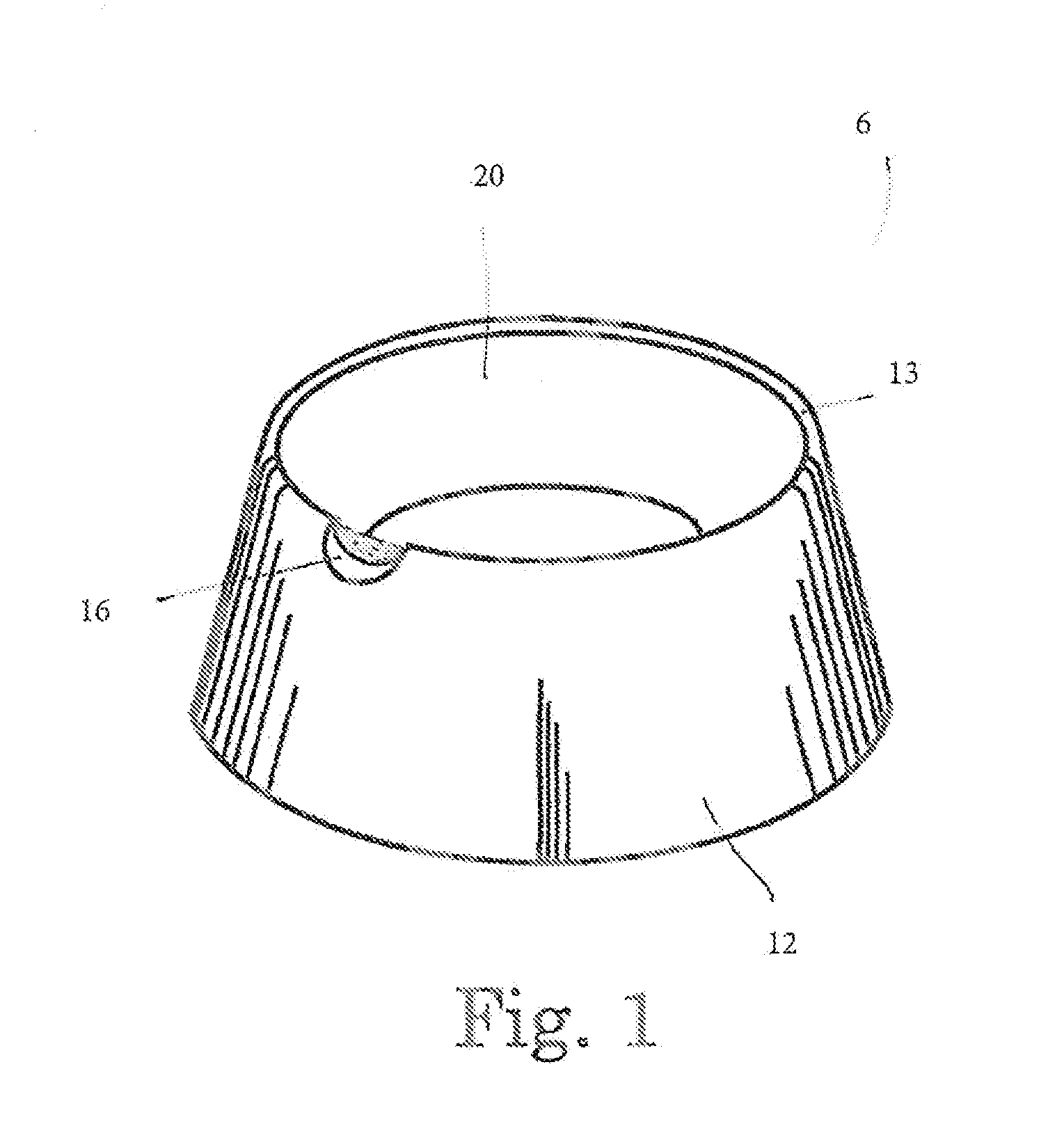
[0042]With reference now to the drawings, FIG. 1 illustrates a pet feeding device 10 in a preferred embodiment. The pet feeding device 10 generally has an outer container 12 having a retaining ridge 13 in a top aspect. At least one liner 20 is shown to be disposed into the outer container 12. A thumb notch 16 is formed out of the outer container 12 and the retaining ridge 13 to facilitate removal of the at least one liner 20.

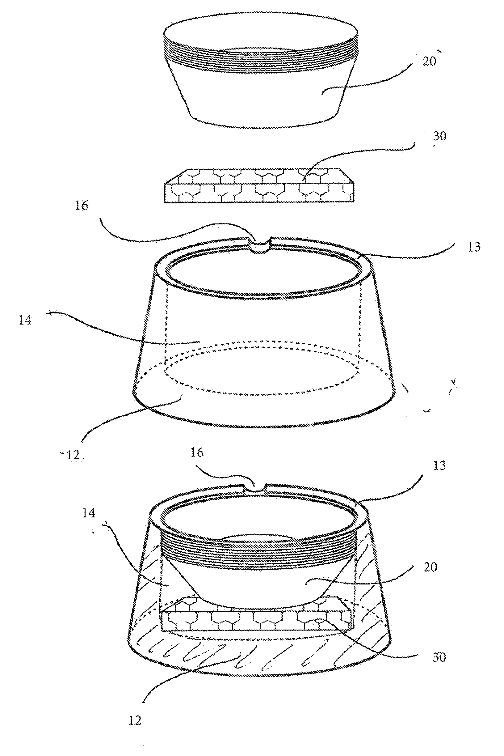
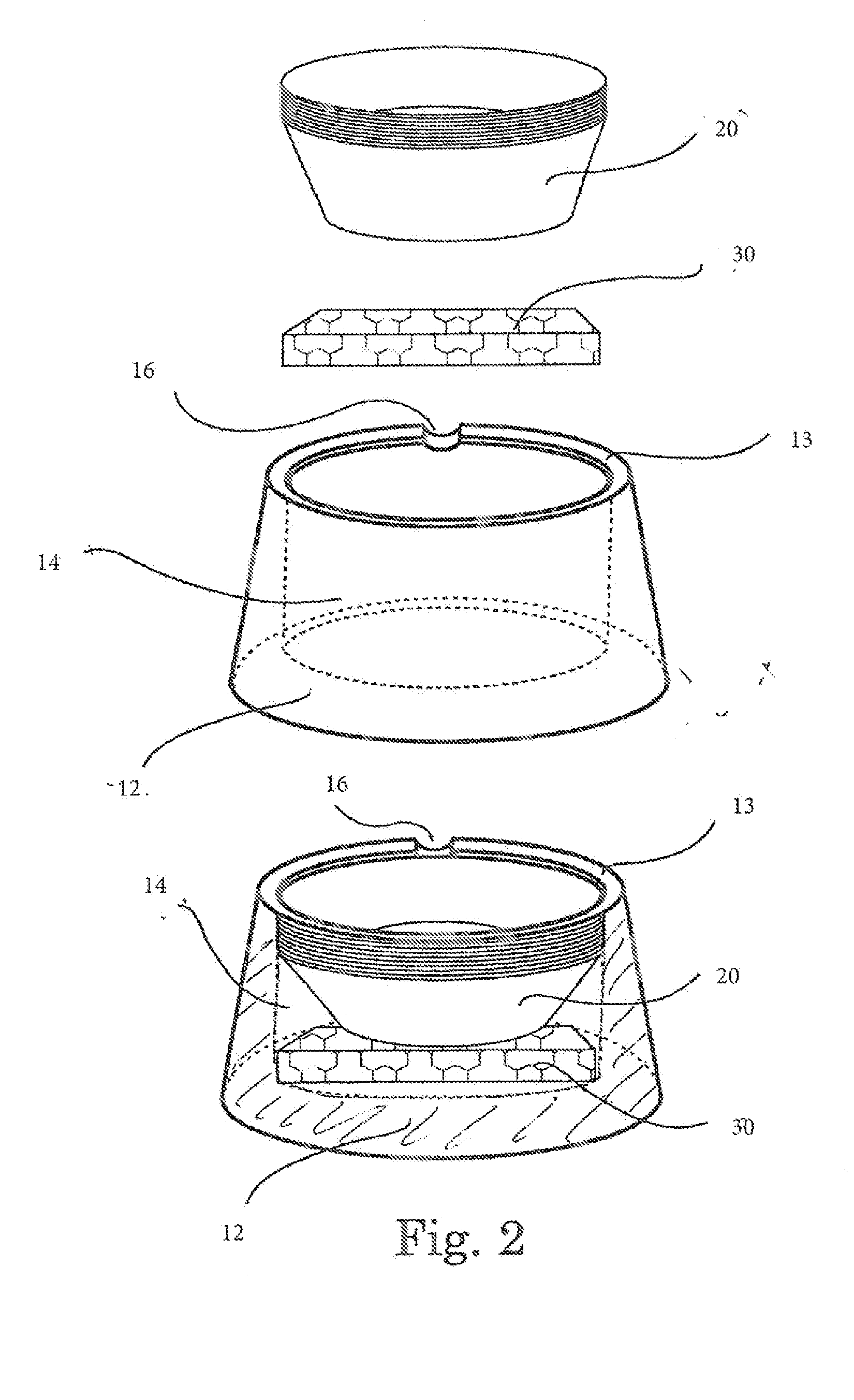
[0043]Regarding FIG. 2, an exploded view of the pet feeding device 10 is shown. The at least one liner 20 is preferably a stacked vertical array of liners. A compression device 30 is configured underneath the at least one liner 20 to provide for a resilient yet pliable material capable in pushing the at least one liner 20 in an upward direction.

[0044]The outer container 12 has an inner surface, an outer surface, a solid bottom and an upper periphery. In a preferred embodiment, the outer container 12 is substantially circular with curved edges. Other configuratio...


PUM


Abstract

A pet feeding device is disclosed having an outer container, an inner cavity within said container, a retaining ridge at the mouth of the inner cavity, a stacked array of at least one liner, and a compression device. The at least one liner can be nested within the inner cavity and then be individually disposed of as required for each new feeding. The at least one liner is held in the inner cavity by the retaining ridge and the compression device. The at least one liner is placed into device for restocking by pressing down into the inner cavity. The at least one liner can be removed for disposal individually. The compression device in bottom of cavity supports liners and continuously keeps supply of the at least one liner conveniently staged at top edge of cavity, as well as keeps them from moving during feedings.

Description

PRIORITY CLAIM[0001]This patent application is a continuation-in-part of copending, non-provisional patent application U.S. patent application Ser. No. 12 / 930,982 by Fairbanks, filed on Jan. 21, 2011, entitled COMBINATION STORAGE, DISPENSING AND FEEDING DEVICE FOR DOMESTIC ANIMALS. This patent application also claims benefit of the priority date of U.S. Prov. Pat. App. Ser. No. 61 / 396,236 by Fairbanks, filed on May 24, 2010, entitled COMBINATION STORAGE, DISPENSING AND FEEDING DEVICE FOR DOMESTIC ANIMALS. The contents of both referenced applications are hereby incorporated in their entirety by reference.FIELD OF THE INVENTION[0002]The present invention generally relates to food bowls. More specifically, the present invention relates to food bowls having disposable liners for serving food to pets, wherein the disposable liners reduce the need to wash the food bowl.BACKGROUND OF THE INVENTION[0003]Traditionally pet owners and other keepers of animals have been faced with the problem o...

Claims


Application Information

Patent Timeline
Patent Type & Authority Applications(United States)
IPC IPC(8): A01K5/01
CPCA01K5/0142A01K5/0128A01K5/0121
Inventor FAIRBANKS, PUTNAM R.
Owner FAIRBANKS PUTNAM R
Learn More