
Modular implant for joint prosthesis

Inactive Publication Date: 2010-05-06
BIOMET MFG CORP
View PDF2 Cites 125 Cited by
  • Summary
  • Abstract
  • Description
  • Claims
  • Application Information

AI Technical Summary

Benefits of technology

[0007]The present invention achieves its objectives by providing cooperating modular prosthetic components that do not occlude the surgeon's access to other adjacent areas that require reconstruction and by reducing the number of modular components required overall. According to the present invention, this is accomplished without sacrificing the stability of the implant by virtue of the modified structure of the support unit, whose structure promotes bony ingrowth into porous portions of the support unit for secure fixation of the prosthetic joint in the humerus that can be used with, or preferably without a traditional stem part.

Problems solved by technology

One drawback associated with the prior art is that after the support unit is impacted in the resected humerus, the upper end of the neck that mates with the humeral head (cap or cup) insert protrudes from the surface that is otherwise flush with respect to the resected humerus.
The protruding shaft part occludes the surgeon's access to the glenoid cavity, and its presence can impede the surgeon's progress with respect to other portions of the implantation process in the glenoid region before the humeral insert (cap or cup) is finally impacted thereon.

Method used


Image

  • Modular implant for joint prosthesis
  • Modular implant for joint prosthesis
  • Modular implant for joint prosthesis

Examples


Embodiment Construction

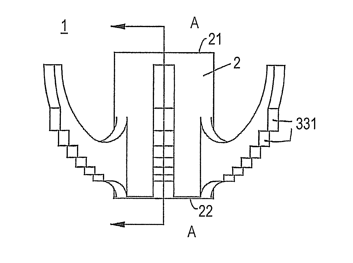
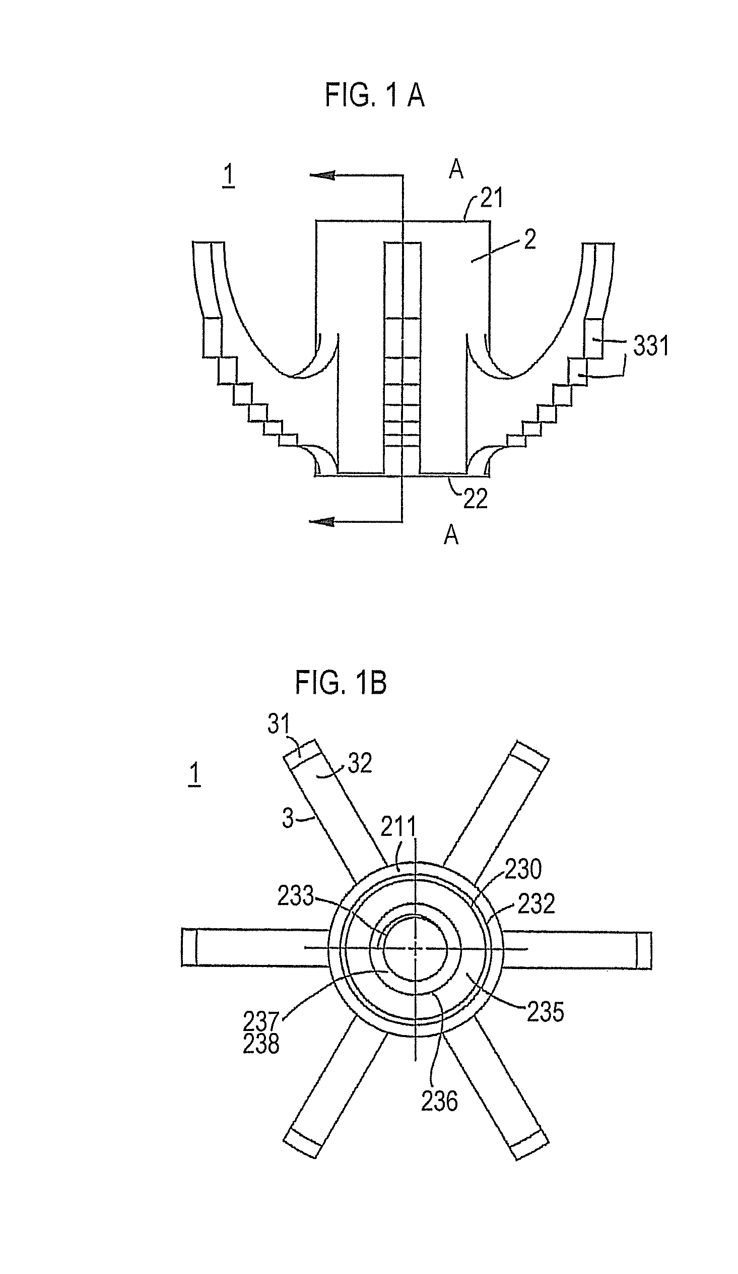
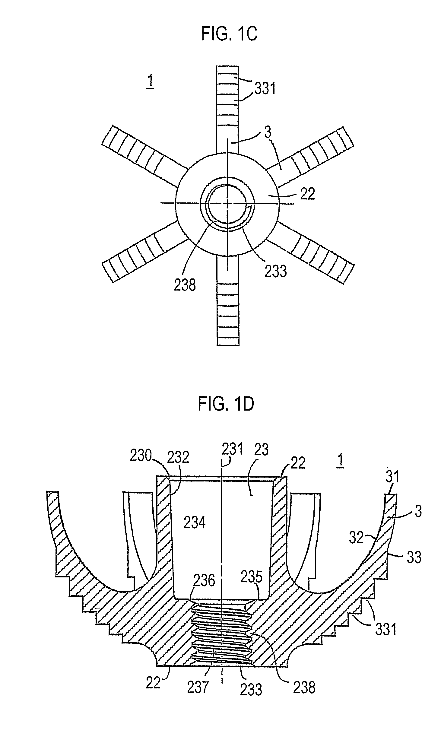
[0035]FIG. 1A is a perspective view of a support cleat unit according to one embodiment of the present invention. FIG. 1B is a top plan view of the support unit shown in FIG. 1A, FIG. 1C is a bottom plan view of the support unit shown in FIG. 1A, and FIG. 1D is a cross-sectional view taken through line A-A in FIG. 1A. FIG. 1E is a perspective view of another support cleat unit according to the present invention, and FIG. 1F is a cross-sectional view of the support cleat shown in FIG. 1E, showing an internal structure of the cylindrical body portion that is different from that shown and described in connection with FIGS. 1A-1D.

[0036]The support cleat unit 1 includes a seat portion 22, which is preferably circular, and has an overall shape delimited by an imaginary domed surface, which is preferably substantially hemispherical in shape with a circular base shape, but which also includes dome shapes having an oblong or oval base shape or the like, as dictated by the physiological requi...


PUM


Abstract

A modular prosthetic implant is provided, including a support cleat unit having a circular seat portion and a shape delimited by an imaginary dome. The support cleat unit includes a cylindrical body portion having a central axis and a hole concentric with the central axis, the hole having a least a first section whose diameter defines a female Morse taper adapted to receive a male member having a corresponding Morse taper. The support cleat unit also includes a plurality of arched appendages integral with the cylindrical body portion. The arched appendages are radially spaced apart from one another and extend outwardly from a base portion thereof at an outer circumferential surface of the cylindrical body portion so that lower / outer surfaces of the arched appendages define the overall domed shape of the support cleat unit.

Description

FIELD OF THE INVENTION[0001]The present invention relates to the field of orthopaedic implants, and in particular, to a modular prosthesis for use in conjunction with partial or total joint replacement procedures, such as humeral and femoral replacement and reconstruction.BACKGROUND OF THE INVENTION[0002]U.S. Pat. No. 7,445,638, the entirety of which is incorporated herein, describes humeral implants that include three separate elements: anchoring stem; a support unit; and one of a cap-shaped humeral head insert or a cup shaped insert, depending on whether partial, full or reverse shoulder reconstruction is required. The stem, which is inserted in the medullary canal of the humerus, is used in conjunction with the support unit to ensure stabilization of the support unit, which, when properly stabilized, functions to anchor the humeral head implant in the humerus.[0003]There are, however, some drawbacks associated with the prior art, and it would be desirable to overcome these drawba...

Claims


Application Information

Patent Timeline
IPC IPC(8): A61F2/30
CPCA61F2/30734A61F2/3601A61F2/3603A61F2/4003A61F2/4607A61F2/4612A61F2002/30332A61F2002/30405A61F2002/30884A61F2002/4022A61F2002/4629A61F2002/4007A61F2/3609A61F2/4014
Inventor WINSLOW, NATHANVANASSE, THOMAS M.
Owner BIOMET MFG CORP
Learn More