Display structure

a technology of display structure and display device, which is applied in the direction of instruments, machine supports, electrical apparatus casings/cabinets/drawers, etc., can solve the problem that the adjusting device cannot adjust the height of the monitor

Inactive Publication Date: 2010-05-27
HONG FU JIN PRECISION IND (SHENZHEN) CO LTD +1
View PDF20 Cites 4 Cited by
  • Summary
  • Abstract
  • Description
  • Claims
  • Application Information

AI Technical Summary

Benefits of technology

[0006]Another typical adjusting device includes a base and a supporting arc-shaped structure. The supporting structure is assembled on the base and extends upwardly from the base. A guide groove is formed on the upper surface of the supporting structure. The monitor can slide in the guide groove and be fastened at different locations to adjust the angle of the monitor. However, the monitor has a fixed height and horizontal orientation.

Problems solved by technology

However, the adjusting device cannot adjust the height of the monitor.

Method used


Image

  • Display structure
  • Display structure
  • Display structure

Examples


Embodiment Construction

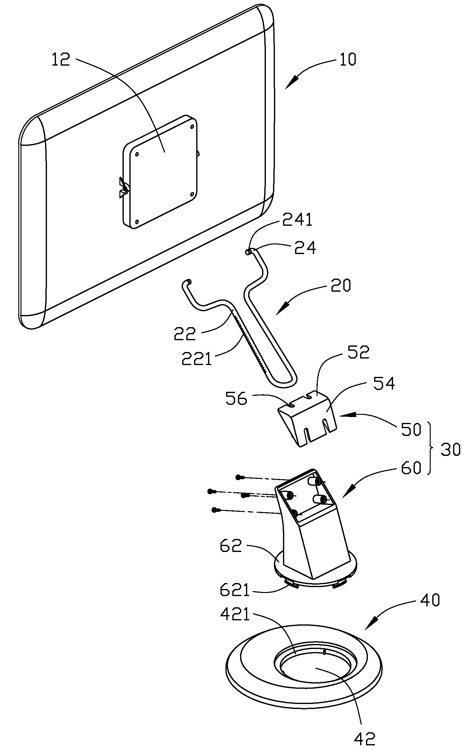
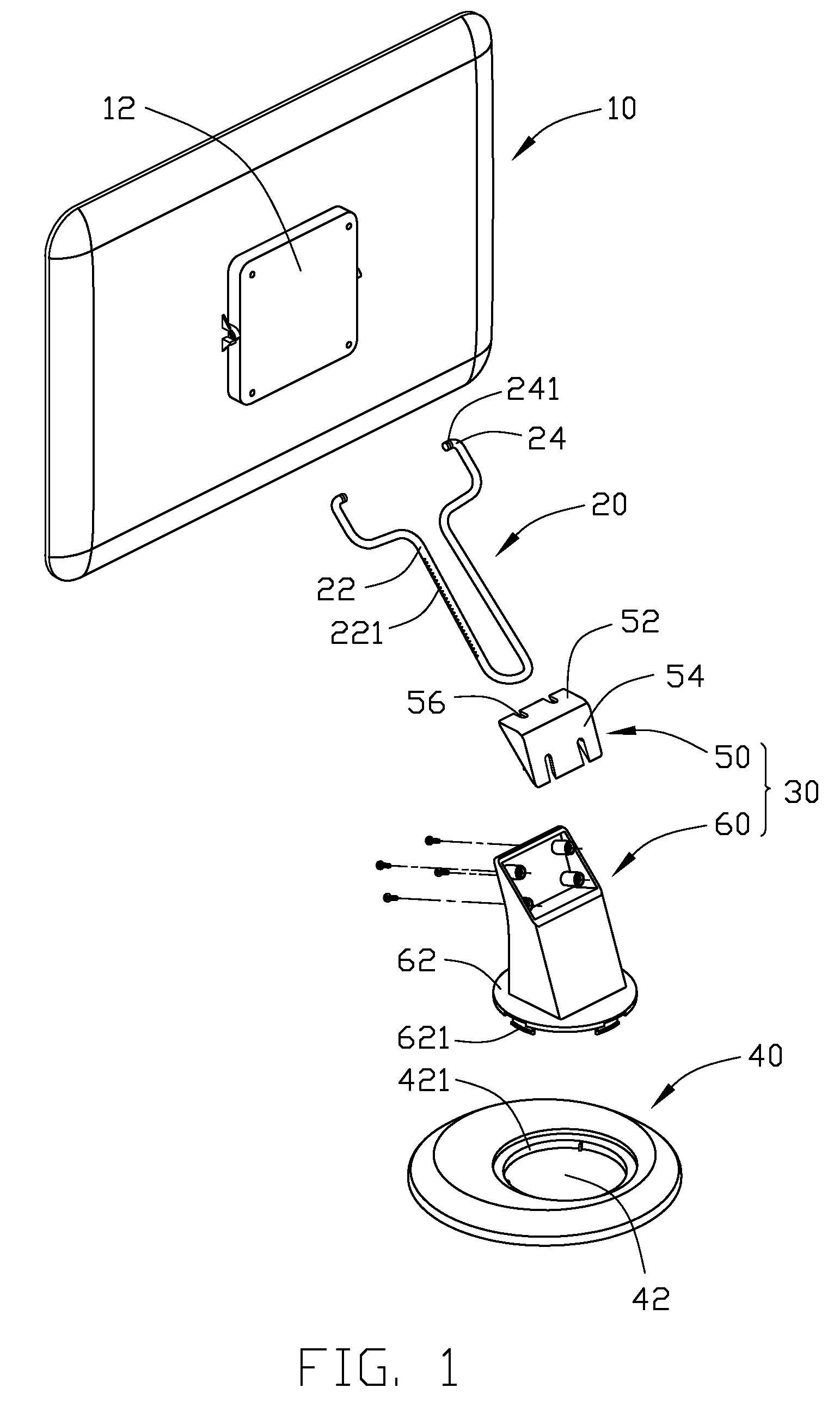
[0013]Referring to FIG. 1, an embodiment of a display structure includes a display unit 10, a connecting member 20, a stand 30, and a base 40. The stand 30 includes a cover portion 50 and a main portion 60.

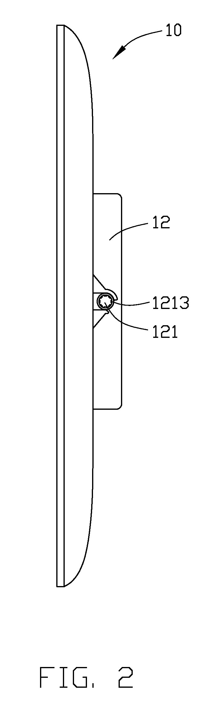
[0014]Referring also to FIG. 2, the display unit 10 includes a protruded portion 12 at a back side thereof. A pair of pivot holes 121 is defined in two sides of the protruded block 12. A plurality of resisting protrusions 1213 is equally positioned around each of the pivot holes 121.

[0015]The connecting member 20 is symmetrically shaped and includes a pair of arm sections 22 and a pair of distal ends 24 engaging in the pivot holes 121 of the display unit 10. At least one of the arm sections 22 defines a plurality of recessed portions 221 therein. Each distal end 24 of the connecting member 20 has an external helical thread 241 engaging with the resisting protrusions 1213 around one of the pivot holes 121. The connecting member 20 may be wire like and elastic.

[0016]Referring to FIG...


PUM


Abstract

A display structure includes a base, a stand pivotably attached to the base and rotatable along a first axis, an elastic connecting member, and a display unit pivotably engaged with ends of the connecting member and rotatable along a second axis substantially perpendicular to the first axis. The connecting member includes a pair of arm sections slidably engaged with the stand for adjusting a height of the display unit.

Description

BACKGROUND[0001]1. Technical Field[0002]The present disclosure relates to display structures and, more particularly, to a display structure with an adjustable supporting device.[0003]2. Description of Related Art[0004]As computer display technology develops, monitors are being developed that are smaller in volume and lighter in weight. A typical adjusting device is assembled thereon to adjust the angle and the height of the monitor.[0005]A typical adjusting device includes a connecting board secured to a back of a monitor, a plate secured to a supporting board, and an active device and a passive device secured to the connecting board and pivotably attached to the plate. The active device is assembled on the plate and can drive the passive device. The connecting board is driven by the passive device to rotate around the supporting board to adjust the horizontal orientation of the monitor. However, the adjusting device cannot adjust the height of the monitor.[0006]Another typical adju...

Claims


Application Information

Patent Timeline
Patent Type & Authority Applications(United States)
IPC IPC(8): H05K7/00
CPCF16M11/10F16M2200/08F16M11/2014Y10S248/917
Inventor CHEN, YUN-LUNGZHANG, ZHONG-HAI
Owner HONG FU JIN PRECISION IND (SHENZHEN) CO LTD
Why Eureka
Try Eureka