Tape loading apparatus

a technology of loading apparatus and tape guide post, which is applied in the direction of data recording, record carrier guidance, instruments, etc., can solve the problems of increasing parts cost, difficulty in ensuring a height precision of several m by simply assembling parts, and increasing the cost of parts, so as to improve the height precision of the tape guide post and the carrier, the effect of reducing cos

Inactive Publication Date: 2007-02-20
PANASONIC CORP
View PDF18 Cites 0 Cited by
  • Summary
  • Abstract
  • Description
  • Claims
  • Application Information

AI Technical Summary

Benefits of technology

[0027]According to one aspect of the present invention, a tape loading apparatus comprises a base, a tape guide post about which a tape is wrapped for tape loading, and a post end contact member provided on the base for fixing the height of the tape guide post by contacting and pressing an end surface of the tape guide post. The position in a height direction of the end surface of the tape guide post is directly fixed by the post end contact portion, so that the height of the tape guide post is fixed. The height precision of the tape guide post with respect to a carrier is independent of the height precision of the tape guidepost. Accordingly, there is no longer need for a base-side reference surface for determining the height of the carrier. Further, the base-side reference surface need not be machined with precision with respect to the height thereof, thereby making it possible to reduce cost. Furthermore, it is possible to remove a factor which causes variations in the height of the tape guide post with respect to the carrier, thereby improving the height precision of the tape guide post. The height precision of the tape guide post with respect to the carrier can be greatly relaxed, thereby making it possible to reduce cost. Even if the height of the tape guide post with respect to the carrier is slightly changed due to aging, tape tension, etc. , the height of the tape guide post is not changed, i. e. , the height of the tape guide post is stable. The slight changes in the height and inclination of the tape guide post with respect to the carrier due to aging, tape tension, etc. can be tolerated, whereby the carrier may not be made of an expensive material and therefore cost can be reduced.
[0028]In one embodiment of this invention, the tape loading apparatus further comprises a post height adjusting member for shifting and adjusting the post end contact member upward and downward to fix the height of the tape guide post. By shifting the post end contact member upward or downward, the height of the tape guide post can approach a predetermined height with a high degree of precision. Further, there is no need for adjusting the height of the tape guide post with respect to the carrier, whereby a height adjusting mechanism or a lateral screw is not required on the carrier side. As a result, the carrier and the tape guide post can be miniaturized and their costs can be reduced. The tape guide post is not rotated in the height adjustment, whereby precession does not occur and the inclination of the tape guide post is not changed. Further, the tape guide post is not rotated in the height adjustment, whereby a hollow portion with which a driver is engaged with an upper flange portion is not required and therefore cost can be reduced.
[0029]In one embodiment of this invention, the tape loading apparatus further comprises a first post engagement member for fixing the position in the plane of the tape guide post by being engaged with an end of the tape guide post. The first post engagement member is continuously integrated with the post end contact member, and comprises a first internal thread portion provided on the first post engagement member, a first hole provided in the post end contact member, and a post height adjusting screw passed through and engaged with the first hole to interlock with the first internal thread portion. As a result, the height of the tape guide post can be adjusted with great precision by the above-described simple structure, i. e. , the formation of the holes and the internal thread portion and the addition of the post height adjusting screw. Therefore, low cost and miniaturization can be realized. Further, since the first post engagement member is continuously integrated with the post end contact member, the number of parts is not increased, the structure is simple, and low cost and miniaturization can be realized.
[0030]In one embodiment of this invention, the first post engagement member is provided with a V-shaped cut, and the cut is engaged with the end of the tape guide post. With the V-shaped cut, the position of the portion of the tape guide post can be determined with a higher degree of precision. Therefore, the reproducibility of the inclination of the tape guide post is excellent, whereby the inclination precision of the tape guide post can be further improved.
[0036]As a result, the height of the tape guide post can be adjusted with great precision by the above-described simple structure, i. e. , the formation of the holes and the internal thread portion, and the addition of the post height adjusting screw and the post inclination adjusting screw. Therefore, low cost and miniaturization can be realized. Further, since the first post engagement member, the post end contact member, and the second posit engagement member are continuously integrated together, the number of parts is small, the structure is simple, and low cost and miniaturization can be realized.
[0037]Thus, the invention described herein makes possible the advantages of providing a tape loading apparatus such that cost can be reduced and miniaturization is easy while the precision which is as well as or better than conventional tape loading apparatuses.

Problems solved by technology

Therefore, it is difficult to guarantee a height precision of several μm by simply assembling parts.
There are, however, the following problems with the above-described conventional arrangement.
Such high precision requires the state of the art machining technology, which leads to an increase in cost for parts.
Therefore, a problem arises in miniaturization.
), leading to problems such as the costs for materials for parts and molding the materials are high.
Parts having insufficient inclination precision are abandoned, resulting in low yield and high cost.
Adequate spacing for the screws on the tape guide post 58 and the carrier side for use in the height adjusting mechanism is required, thereby making it difficult to design a small carrier and tape guide post.
As a result, it is difficult to obtain a small mechanism.
Therefore, such screws have to be shaped by thread cutting, leading to an increase in cost.
It is impossible to manufacture a tape guide post such that the lower portion of the tape guide post supported by a carrier is perfectly in parallel to the tape guide portion of the tape guide post.
Therefore, the height adjustment changes the inclination of the tape guide portion with respect to the base, thereby reducing the inclination precision of the tape guide post.
, thereby increasing cost.
Thus, a slot or hexagonal hollow portion is provided at the upper flange portion, thereby increasing cost (in FIG. 9, no hollow portion is shown at the upper flange portion, but a hollow portion is generally provided at the upper flange portion so as to rotate the tape guide post).
Therefore, fluctuation of tape tension slightly modifies the inclination and height of a tape guide post, whereby the inclination and height of the tape guide post become unstable.
A thicker carrier is required in order to minimize such variations, but the larger size inhibits miniaturization.

Method used


Image

  • Tape loading apparatus
  • Tape loading apparatus
  • Tape loading apparatus

Examples


example

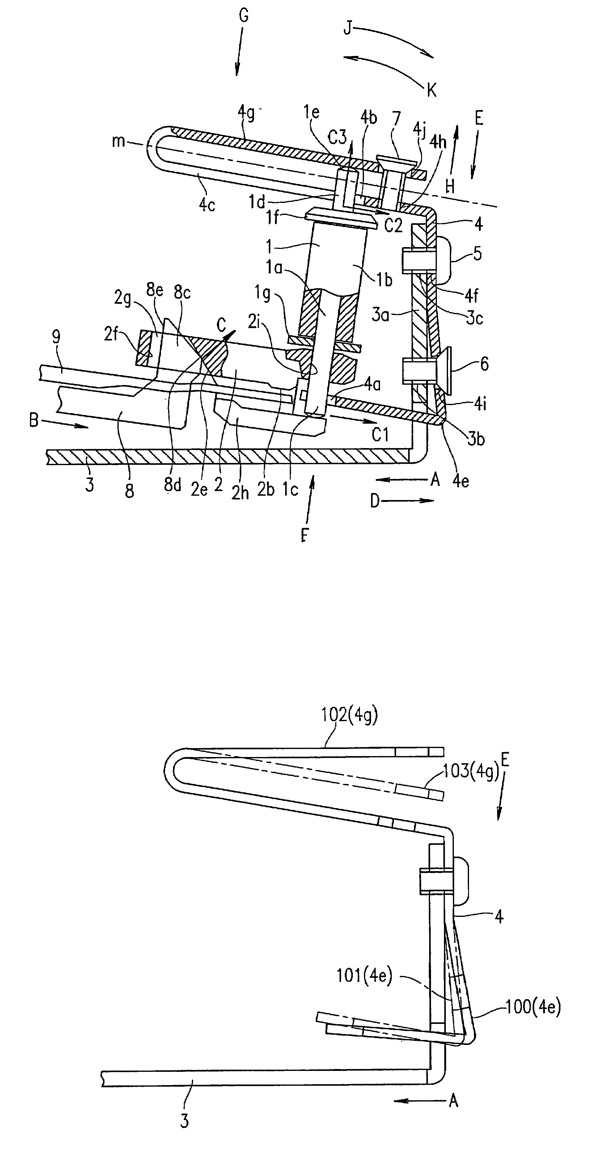
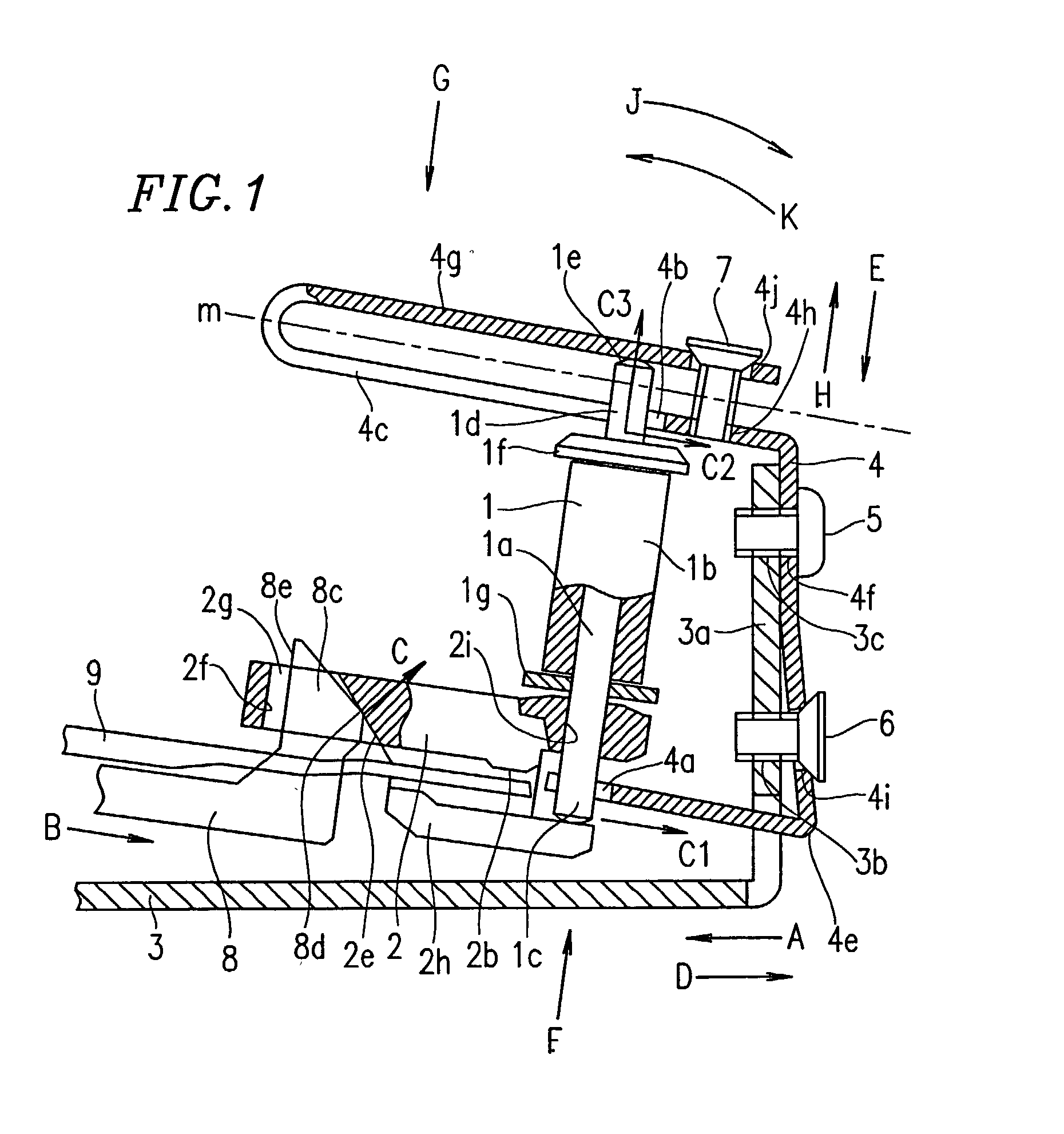
[0049]FIG. 1 is a diagram showing a tape loading apparatus in relevant part according to an example of the present invention. It should be noted that FIG. 1 shows the tape loading apparatus for use in a magnetic recording / reproduction apparatus, particularly indicating the positioning of tape guide posts in the running of a magnetic tape. The steps from withdrawal of a magnetic tape out of a cassette to formation of a predetermined tape running system, and a function of guiding the magnetic tape are substantially the same as those in conventional technology. Therefore, portions of the tape loading apparatus having substantially the same arrangements or functions as those in conventional apparatuses are not described, and only portions which are characteristically distinguished from conventional apparatuses will be described below.

[0050]Referring to FIG. 1, a tape guide post 1 comprises a roller shaft 1a, a roller 1b rotatably supported by the roller shaft 1a, an upper flange 1f fixe...


PUM

PropertyMeasurementUnit
widthaaaaaaaaaa
heightaaaaaaaaaa
heightaaaaaaaaaa

Abstract

A tape loading apparatus comprises a base, a tape guide post about which a tape is wrapped for tape loading, and a post end contact member provided on the base for fixing the height of the tape guide post by contacting and pressing an end surface of the tape guide post.

Description

BACKGROUND OF THE INVENTION[0001]1. Field of the Invention[0002]The present invention relates to a tape loading apparatus for use in a magnetic recording / reproduction apparatus, such as a video tape recorder (VTR).[0003]2. Description of the Related Art[0004]Recently, recording density has increased as magnetic recording / reproduction apparatuses, such as VTRs, etc. , have become digital and miniaturized. As a result, there is a demand for an improved precision tape running system. Of course, a high degree of precision is required for a tape loading apparatus. For audiovisual products, there is a trend toward reduced size and cost. The same is true of magnetic recording / reproduction apparatuses, such as VTRs, etc.[0005]A conventional tape loading apparatus will be described below. For example, Japanese Patent No. 2701575 discloses a conventional tape loading apparatus. FIGS. 5, 6 and 7A through 7D illustrate this conventional tape loading apparatus for use in a VTR. These figures are...

Claims


Application Information

Patent Timeline
Patent Type & Authority Patents(United States)
IPC IPC(8): G11B15/61G11B15/60G11B15/665
CPCG11B15/6656G11B15/61
Inventor KONISHI, AKIOHIRABAYASHI, KOICHIRO
Owner PANASONIC CORP
Why Eureka
Try Eureka