Microphone stand and microphone stand set

a microphone stand and microphone technology, applied in the direction of stand/trestle, mouthpiece/microphone attachment, machine support, etc., can solve the problem that not all users have a camera stand or a suitable height, and achieve the effect of simple operation, convenient adjustment of the height of the microphone stand, and reduced cos

Active Publication Date: 2017-10-03
D & M HOLDINGS INC
View PDF11 Cites 0 Cited by
  • Summary
  • Abstract
  • Description
  • Claims
  • Application Information

AI Technical Summary

Benefits of technology

[0017]The microphone stand according to the present invention includes the first tubular part and the second tubular part, which are connected together in the height direction of the microphone stand by the slidable insertion of one into the other. Therefore, the height of the microphone stand can be easily adjusted by a sliding operation of those two tubular parts. The first tubular part has the plurality of first cutouts, in each of which the middle portion projects outward from the straight line connecting both the ends, and which are formed at intervals in the height direction of the microphone stand. The second tubular part has the cutout formed so as to be positionally aligned with any one of the plurality of cutouts in the first tubular part. Therefore, without separately preparing a special stopper, the height of the microphone stand can be fixed by arranging the cord of the microphone inside the two cutouts positionally aligned with each other by the sliding operation of the two tubular parts, or by pushing the edge portion of one cutout into the other cutout. Therefore, the microphone stand capable of height adjustment with a simple operation can be provided at lower cost.

Problems solved by technology

However, not all users have a camera stand or a stand having a suitable height.

Method used


Image

  • Microphone stand and microphone stand set
  • Microphone stand and microphone stand set
  • Microphone stand and microphone stand set

Examples


Embodiment Construction

[0023]An embodiment of the present invention is described below with reference to the drawings.

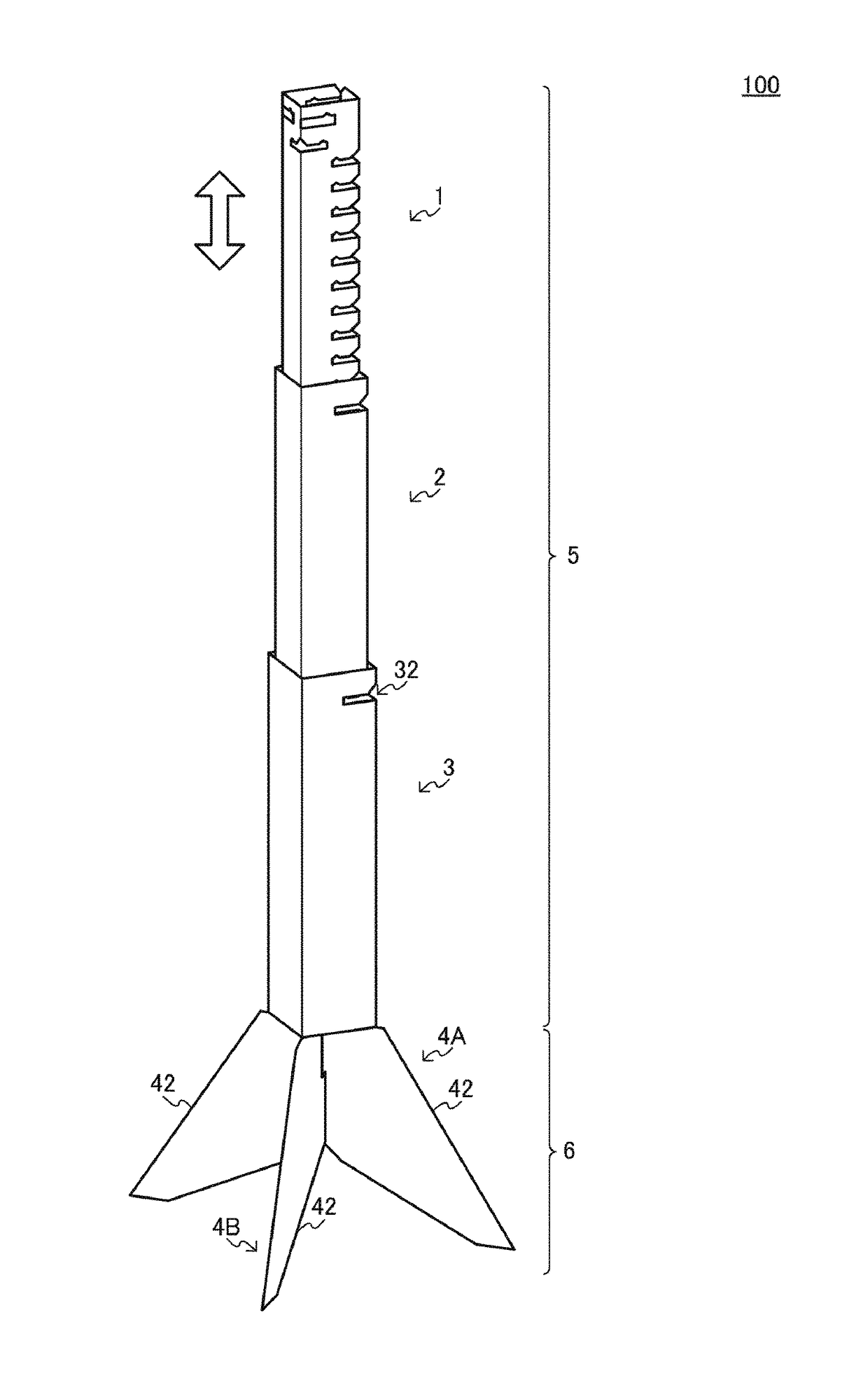
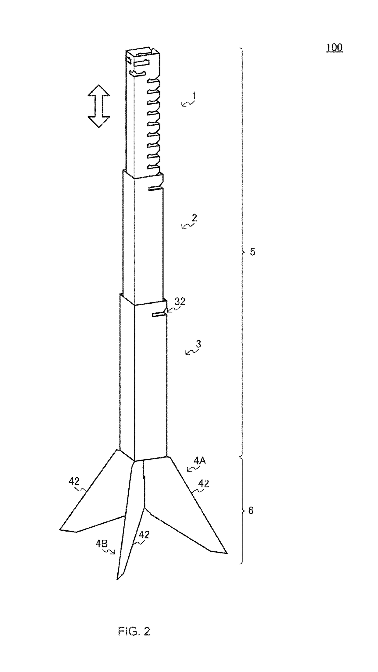
[0024]The overall structure of a microphone stand 100 according to this embodiment is first described. A case of using a microphone 7 for acoustic characteristic measurement, which has a quadrangular pyramid-shaped casing, as a microphone for acoustic characteristic measurement, which is located at a listening position in a setup of a multichannel audio system including a plurality of speakers, is taken as an example.

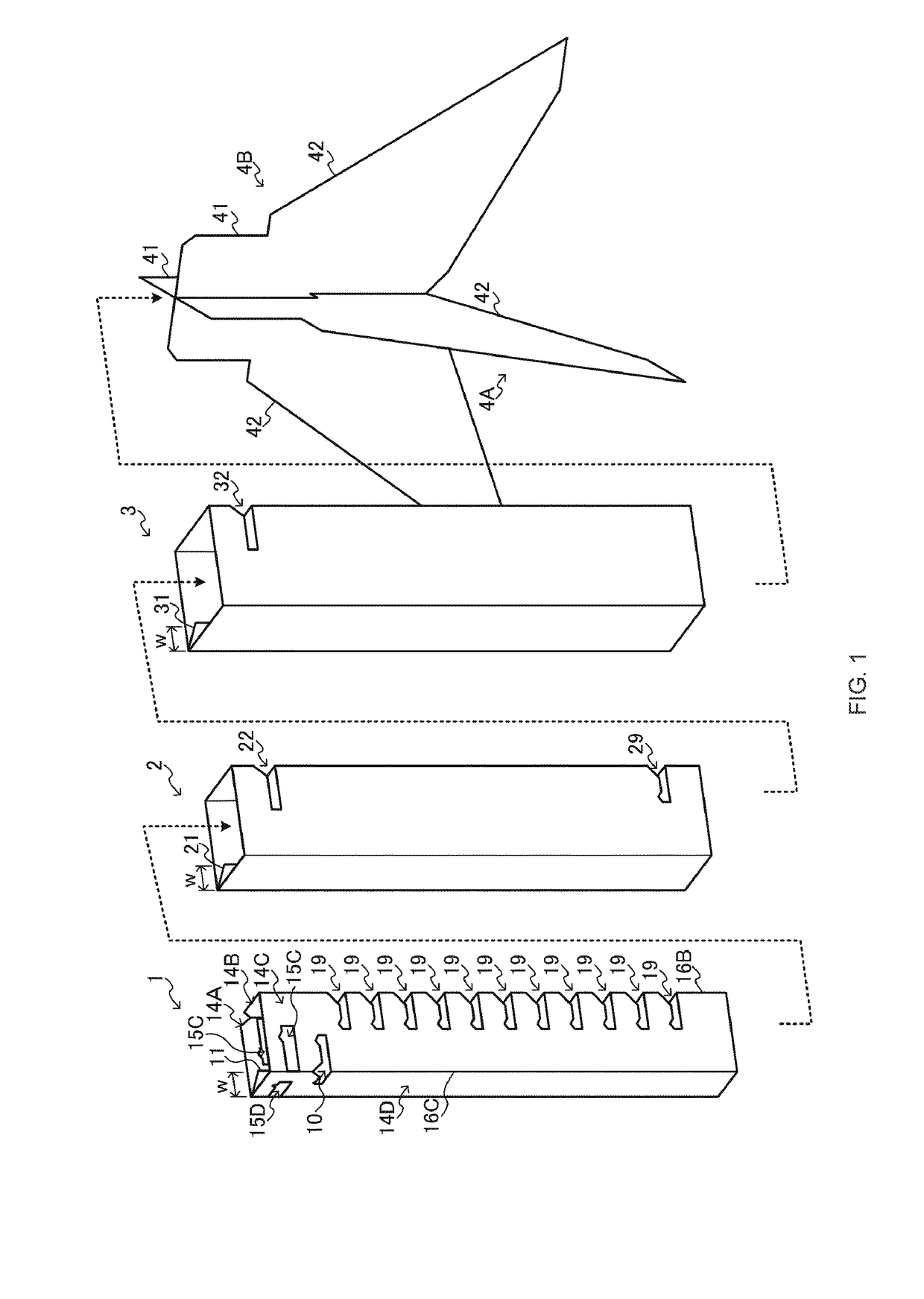
[0025]FIG. 1 is a view for illustrating appearances of parts 1 to 3, 4A, and 4B included in a microphone stand set according to this embodiment and an assembly procedure thereof. FIG. 2 is an external view of the microphone stand 100 assembled from the microphone stand set. FIG. 3(A) to FIG. 3(D) are views for illustrating a procedure for mounting the microphone 7 for acoustic characteristic measurement to the microphone stand 100. FIG. 4(A) to FIG. 4(C) are partial enlarged v...


PUM


Abstract

[Problem] To provide, at a lower cost, a microphone stand the height of which can be adjusted by an easy operation.[Solution] A support strut (5) of an acoustic characteristic measurement microphone comprises two rectangular-tube-shaped attachment parts (1, 2) that are attached to each other in the axis direction by inserting one of the attachment parts into the other such that the one can slide within the other in the axis direction. A plurality of height adjustment slits (19) that are aligned in the height direction of the microphone stand are formed in a corner portion of the one attachment part (1). In the other attachment part (2), an attachment slit (22) is formed at a position where the plurality of height adjustment slits (19) pass due to the sliding of the two attachment parts (1, 2) in the height direction of the microphone stand. A cord (71) of the acoustic characteristic measurement microphone (7) placed on the top of the microphone stand is pushed into and fixed to the interior of two slits (19, 22) that have been positioned by the sliding of the two attachment parts.

Description

CROSS-REFERENCE TO RELATED APPLICATIONS[0001]This application is the National Stage of International Application No . PCT / JP2014 / 060672, filed Apr. 15, 2014, which claims the benefit of Japanese Patent Application No. 2013-240478, filed Nov. 20, 2013. The contents of these prior applications are incorporated by reference herein in their entirety.TECHNICAL FIELD[0002]The present invention relates to the structure of a microphone stand suitable to mount a microphone for acoustic characteristic measurement, which is located at a listening position in a setup of a multichannel audio system and other systems.BACKGROUND ART[0003]In a setup of a multichannel audio system including a plurality of speakers, a listening environment at a listening position may be optimized by arranging a microphone for acoustic characteristic measurement at the listening position and collecting test signals output from the respective speakers with the microphone for acoustic characteristic measurement. An exam...

Claims


Application Information

Patent Timeline
Patent Type & Authority Patents(United States)
IPC IPC(8): H04R1/08F16M11/22F16M11/24F16M11/28
CPCH04R1/08F16M11/22F16M11/24F16M11/28F16M2200/028
Inventor KITAKAMI, YASUHARUWACHTER, MARTIN RICHARD
Owner D & M HOLDINGS INC
Why Eureka
Try Eureka