
Visual guidance for vehicle navigation system

a vehicle navigation and visual guidance technology, applied in the direction of traffic control systems, navigation instruments, instruments, etc., can solve the problems of preventing the driver from accurately seeing, difficult to make different turning decisions, and poor visibility

Active Publication Date: 2010-05-27
GM GLOBAL TECH OPERATIONS LLC
View PDF7 Cites 44 Cited by
  • Summary
  • Abstract
  • Description
  • Claims
  • Application Information

AI Technical Summary

Benefits of technology

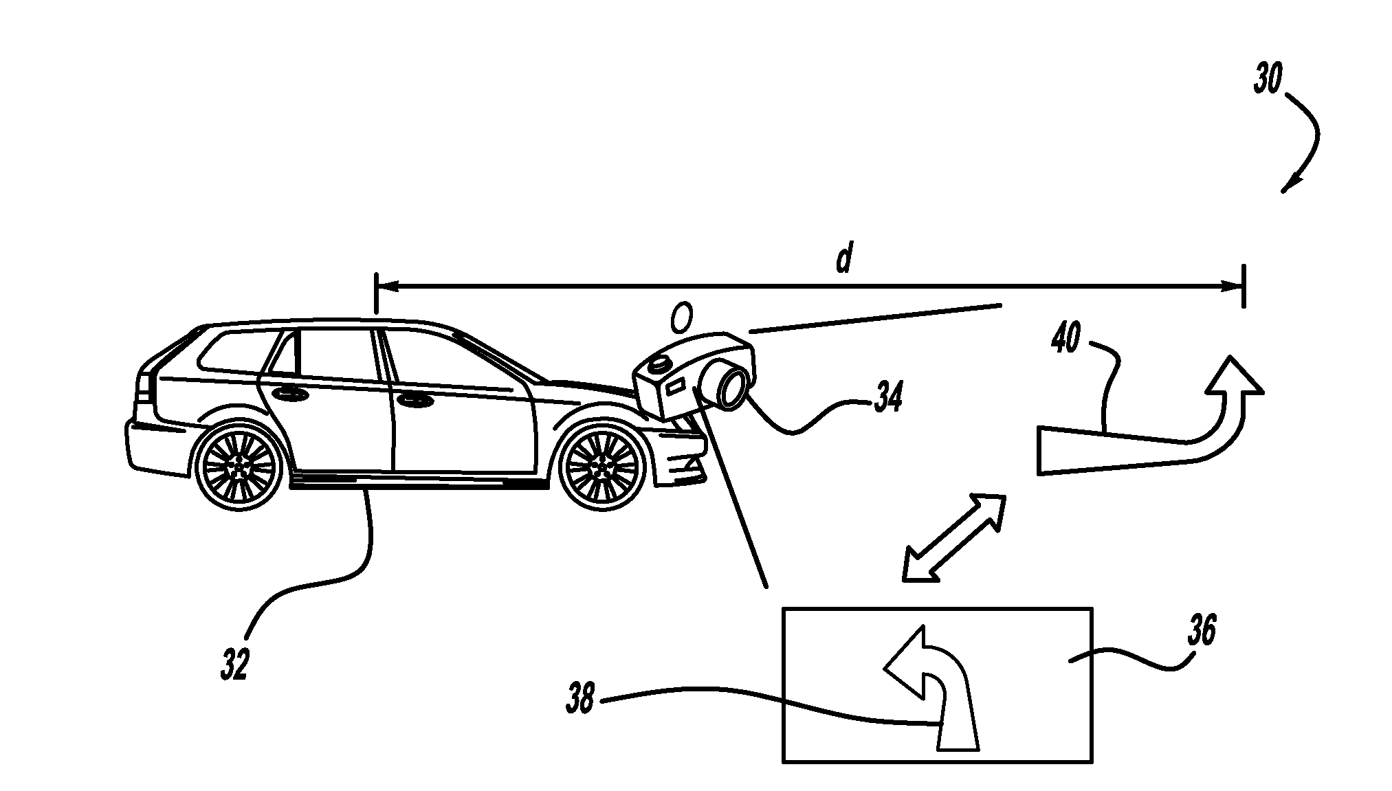
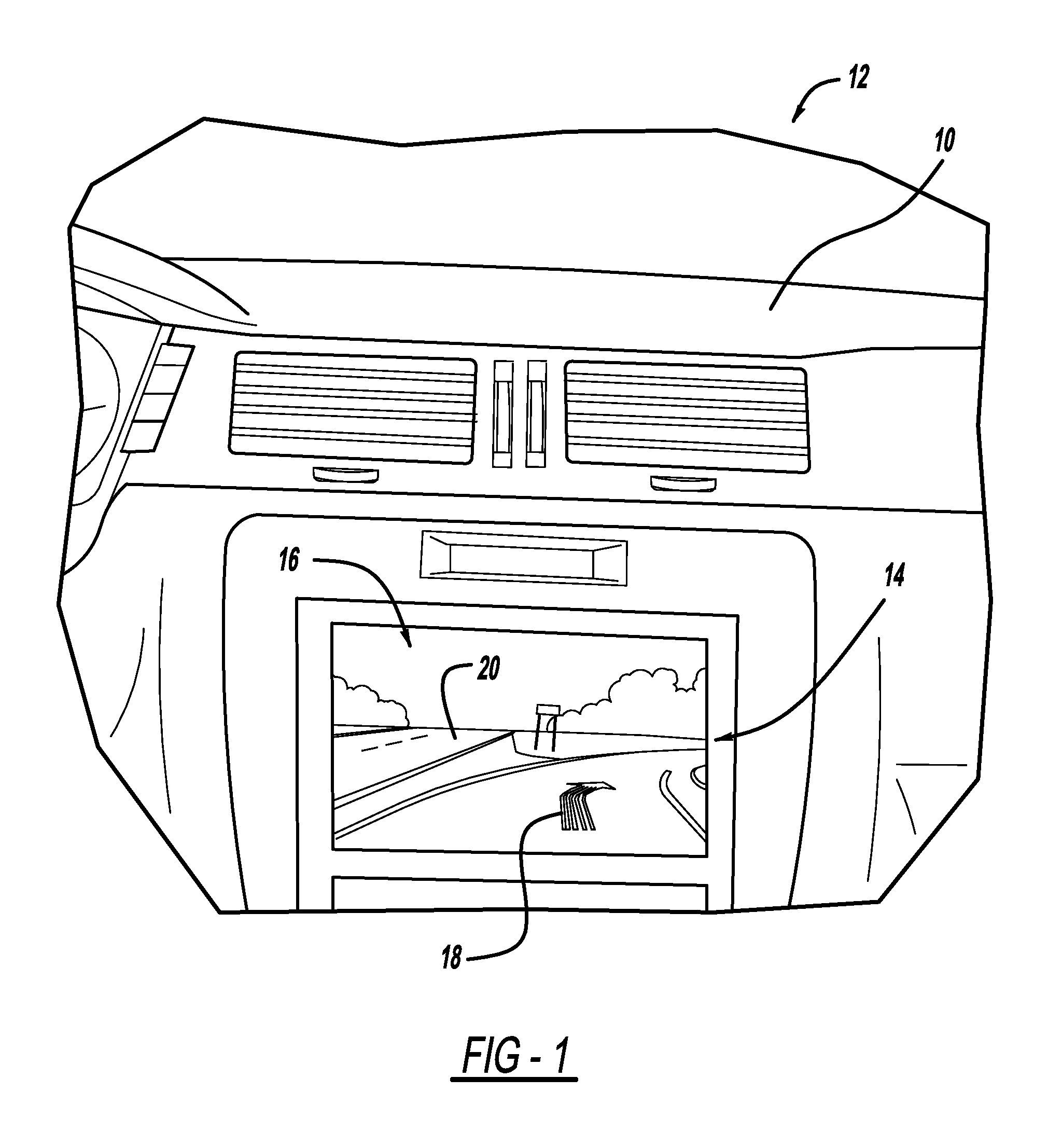
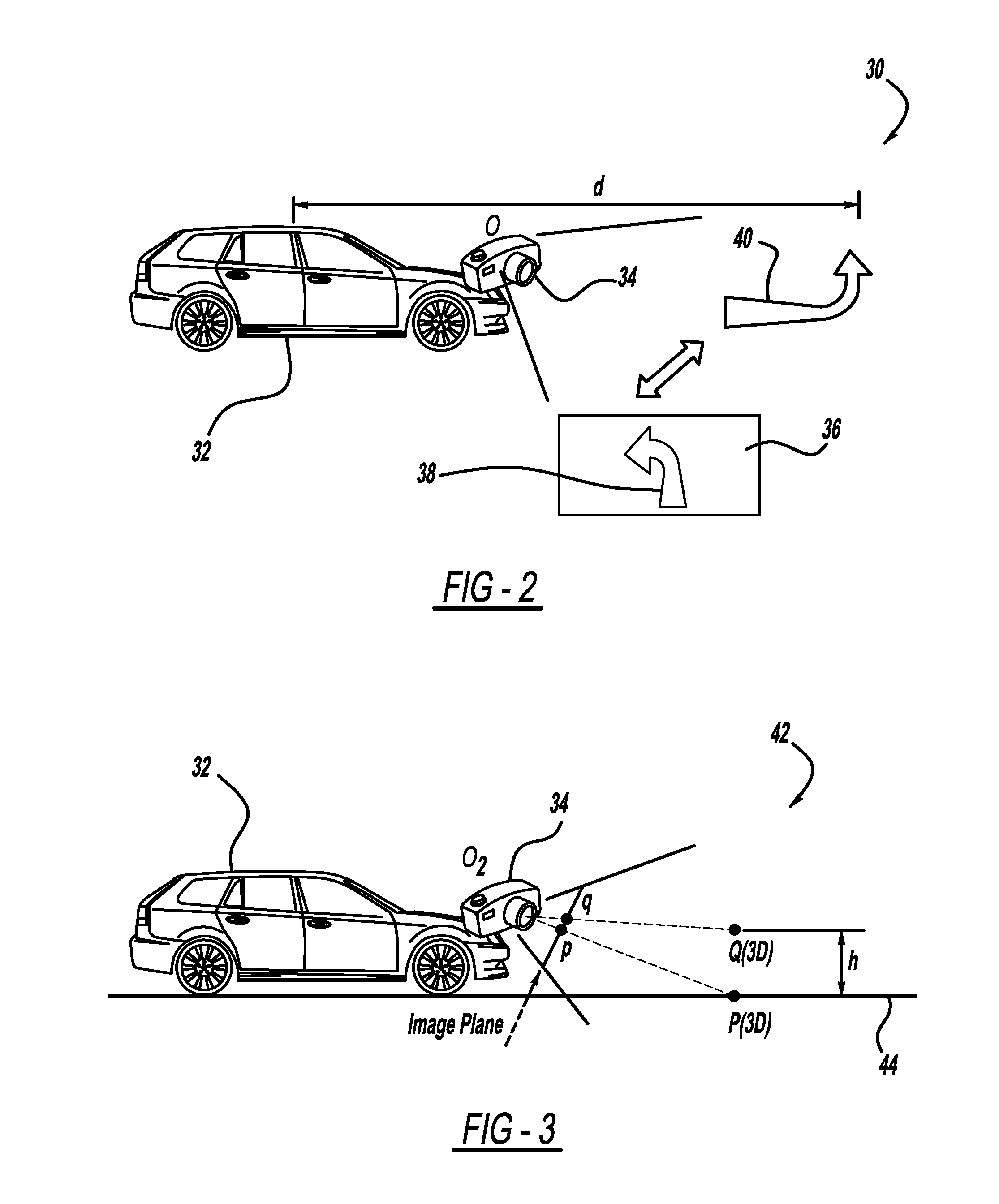
The present invention is a video-based vehicle navigation system that uses an arrow on the video display to guide the driver to their destination. The system determines the proper position of the guidance arrow based on information like GPS position, range measurements, and map information. The camera is calibrated to the ground using various techniques to ensure accurate navigation. The technical effect of this invention is to provide a more intuitive and accurate navigation system for drivers.

Problems solved by technology

However, various circumstances and driving conditions, even when using a navigation system, still make various turning decisions difficult.
For example, night time driving and / or inclement weather conditions may provide poor visibility and prevent the driver from accurately seeing a turn and the direction of the turn even when aided by the graphics display and the audio assist.
Further, many intersections include multiple travel lanes and / or multiple turning directions that the driver can follow, which may be confusing.
Further, street markers may not adequately identify a street at an intersection.
Also, following behind an obstacle, such as a large truck, may block the driver's view at an intersection.
Therefore, current navigation systems may not be fully adequate.

Method used


Image

  • Visual guidance for vehicle navigation system
  • Visual guidance for vehicle navigation system
  • Visual guidance for vehicle navigation system

Examples


Embodiment Construction

[0012]The following discussion of the embodiments of the invention directed to a system and method for overlaying a guidance arrow onto a video-based display in connection with a vehicle navigation system is merely exemplary in nature, and is in no way intended to limit the invention or its applications or uses.

[0013]As will be discussed below, the present invention proposes a vehicle navigation system that is enhanced by employing a camera that provides a video-based image of the road in front of the vehicle and a guidance arrow superimposed on the image showing which direction a vehicle driver should follow in response to following a particular navigation route. As will be discussed in detail below, the video image from the camera will be displayed on a display screen and be overlaid with the guidance arrow showing a direction of vehicle travel to follow a particular route. The question as to whether the video image will always be displayed during route navigation, or whether the ...


PUM


Abstract

A system and method that provide a video-based vehicle navigation system. The system positions an arrow on the video display that shows the specific turning direction for the vehicle for route guidance purposes. To determine the proper position of the guidance arrow, the process determines a distance from the current vehicle position to the location where the vehicle needs to turn using any suitable information, such as GPS position, range measurements and map information. The process then positions the guidance arrow on the ground at the turning location in world coordinates, and projects the guidance arrow onto the image. The camera can be calibrated to the ground using various techniques, such as an online automatic calibration process that uses detected objects in the scene around the vehicle.

Description

BACKGROUND OF THE INVENTION[0001]1. Field of the Invention[0002]This invention relates generally to a system and method for providing a visual display identifying a vehicle turning direction and, more particularly, to a system and method for providing an arrow superimposed on a camera based visual display that shows a turning direction for a vehicle in association with route guidance for a vehicle navigation system.[0003]2. Discussion of the Related Art[0004]Navigation systems for vehicles are well known in the art. Navigation systems typically allow a vehicle driver to identify a desired destination, such as by providing a specific address. The navigation system will then use GPS information and map databases to calculate a route from the vehicle's current position to the destination along the roads available from the map database. As the vehicle is driven along the route to the destination, map graphics are displayed on a display screen in the vehicle along with an icon showing th...

Claims


Application Information

Patent Timeline
Patent Type & Authority Applications(United States)
IPC IPC(8): G01C21/36G06K9/00
CPCG01C21/3647G01C21/36
Inventor ZHANG, WENDESADEKAR, VARSHA
Owner GM GLOBAL TECH OPERATIONS LLC
Learn More