
Apparatus and method for designing a system specification for testability

a system specification and testability technology, applied in the field of apparatus and a method for designing a system specification for testability, can solve the problems of difficult verification and correction of a consistent behavior specification between adjacent components, difficult to create software of high quality, and inability to process restriction of behavior

Inactive Publication Date: 2010-05-27
KK TOSHIBA
View PDF10 Cites 16 Cited by
  • Summary
  • Abstract
  • Description
  • Claims
  • Application Information

AI Technical Summary

Benefits of technology

The present invention is about a system that can be tested and verified to ensure it works properly. The invention includes an apparatus that stores the connection between components in a system and their input and output actions. It also stores the behavior of each component, including how it responds to different inputs. The apparatus can then create a path that describes how the components interact and how they produce output. The invention also includes a verification unit that checks if the output of one component satisfies the input of another component. If there is a problem, the invention can fix it by either relaxing or tightening the input of the component. Overall, the invention allows for easier testing and verification of a system's specification.

Problems solved by technology

Accordingly, it is difficult to create the software having high quality.
Accordingly, in case of installing each component into an entire system, it is difficult to verify and correct a consistency of the behavioral specification between adjacent components.
Furthermore, when a new behavior is generated by combining components, a restriction of the behavior cannot be processed.
However, when a scale of the object system becomes large, a state explosion occurs.
Especially, in a distributed system operating in parallel, a problem of state explosion is remarkable.

Method used


Image

  • Apparatus and method for designing a system specification for testability
  • Apparatus and method for designing a system specification for testability
  • Apparatus and method for designing a system specification for testability

Examples


Embodiment Construction

[0028]Hereinafter, embodiments of the present invention will be explained by referring to the drawings. The present invention is not limited to the following embodiments.

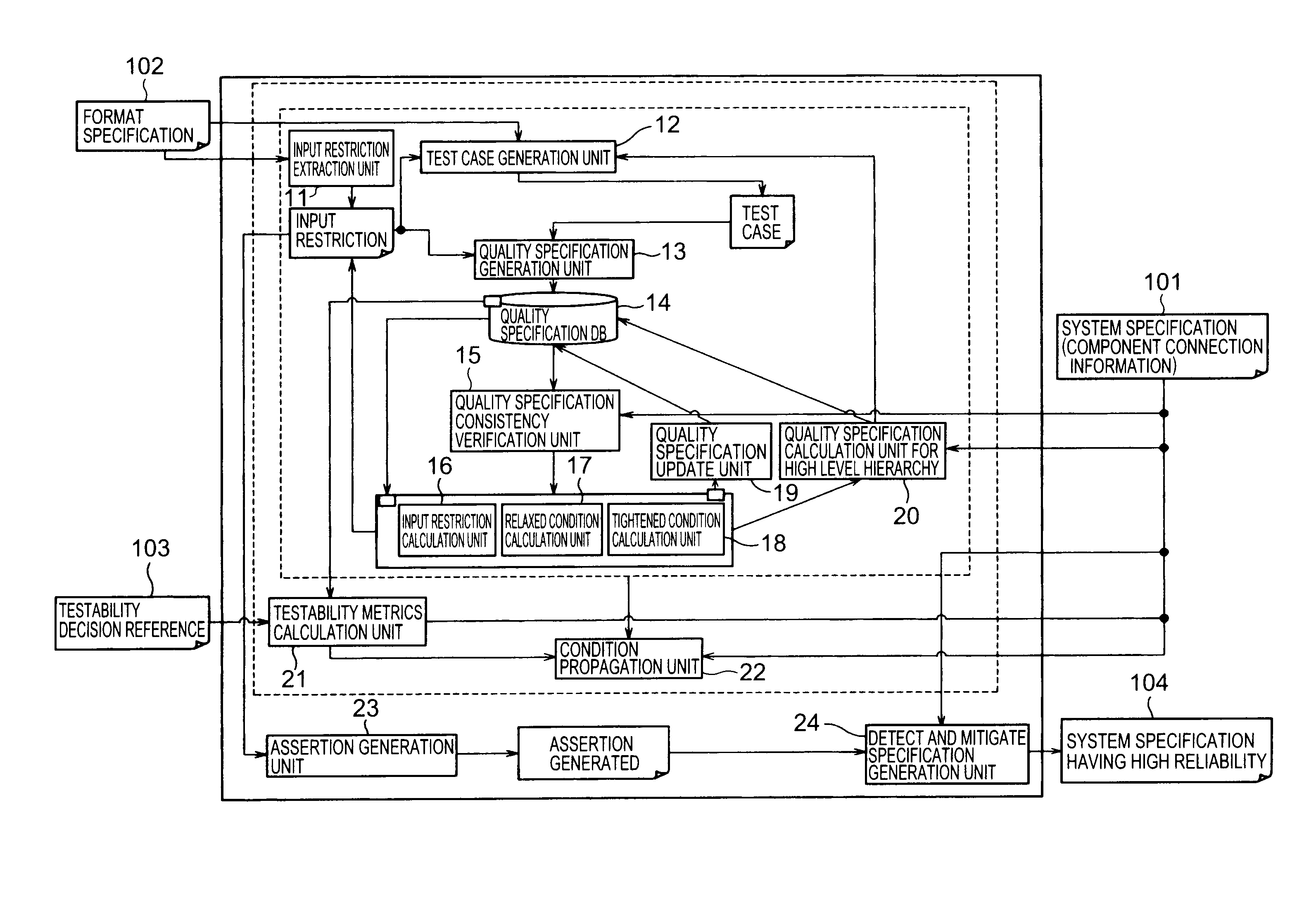
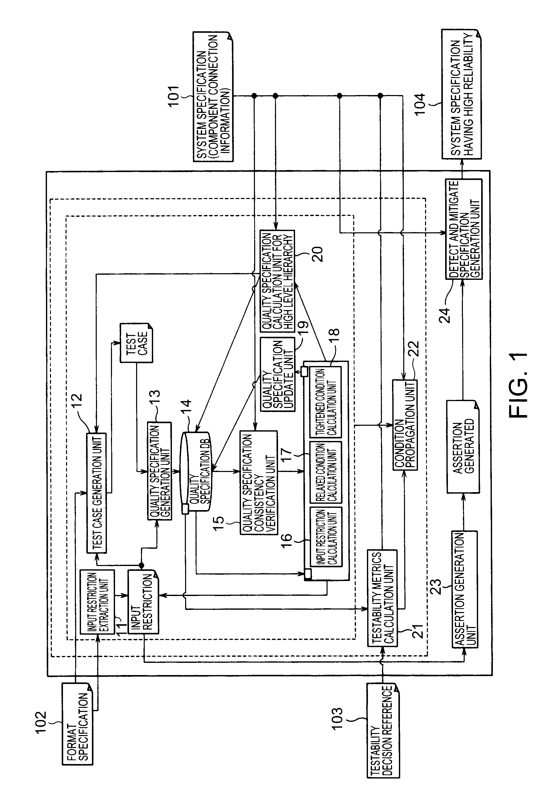
[0029]FIG. 1 is a block diagram of the apparatus for designing a system specification for testability according to one embodiment. This apparatus reads a system specification 101 of an object system and a format specification 102 including a behavioral specification of each component composing the object system, and receives as input data.

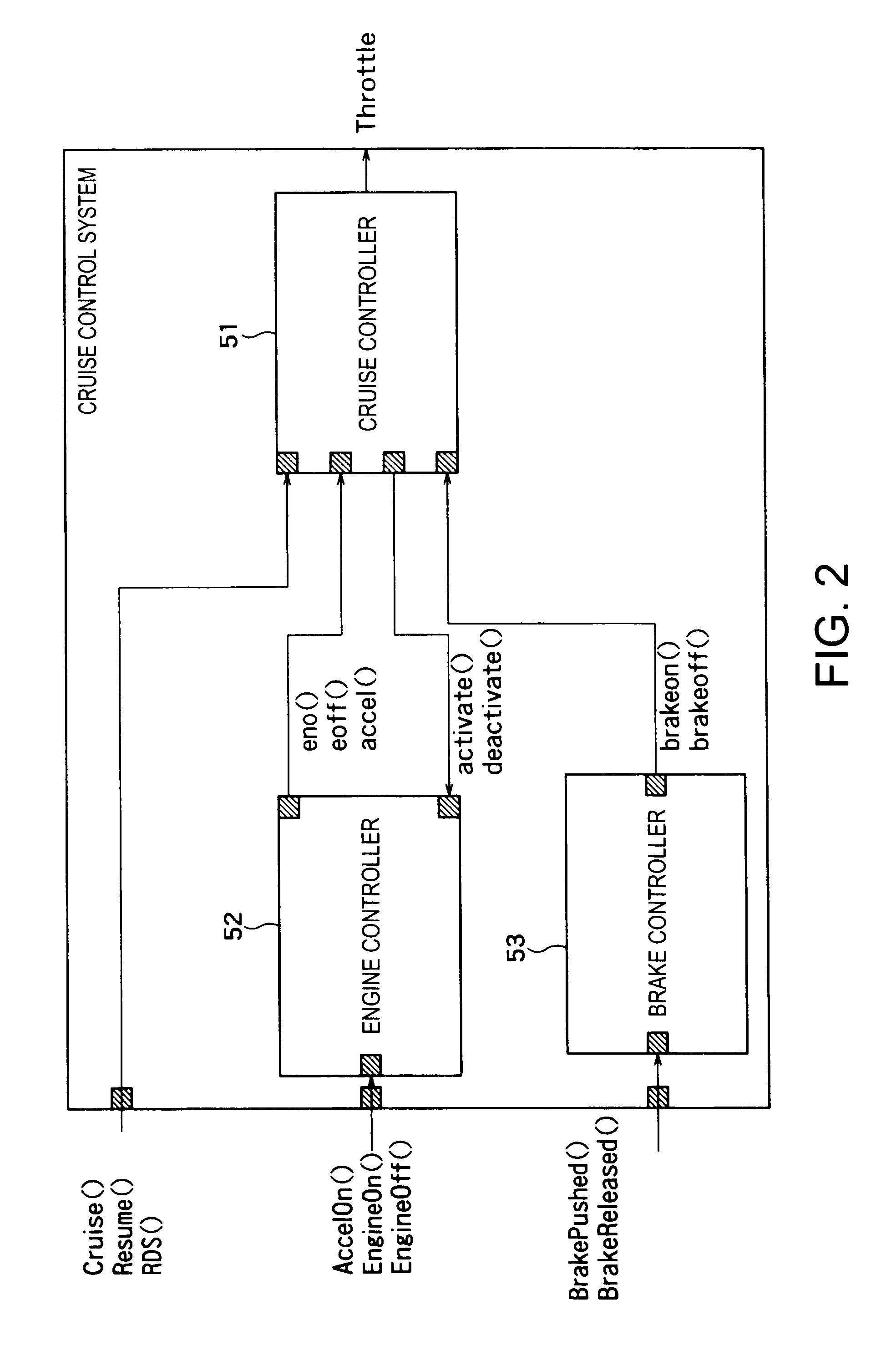
[0030]FIG. 2 is a block diagram of a cruise control system as one example of the object system described in the system specification 101. The cruise control system includes a cruise controller 51, an engine controller 52 and a brake controller 53.

[0031]The cruise controller 51 receives each action of an engine-on (eon), an engine-off (eoff) and an accel-on (accel) from the engine controller 52. Furthermore, the cruise controller 51 receives each action of a brake-on (brakeon) and a...


PUM


Abstract

As to a plurality of components in a system, a state transition path covering transitions defined by a behavioral specification of a component is specified to satisfy an input restriction of the component. Action sequences are acquired from the state transition path. By selecting a pair of components connected in the system, it is verified whether an output action sequence of a first component as one of the pair satisfies an input restriction of a second component as the other of the pair. If unsatisfied, the input restriction of the second component is relaxed to satisfy the output action sequence of the first component, or an input restriction of the first component is tightened to acquire a new output action sequence satisfying the input restriction of the second component. Above processing is repeated for each pair of components, so that output action sequences of one and the other of a pair satisfies input restrictions of the other and the one of the pair respectively.

Description

CROSS-REFERENCE TO RELATED APPLICATIONS[0001]This application is based upon and claims the benefit of priority from Japanese Patent Application No. 2008-299849, filed on Nov. 25, 2008; the entire contents of which are incorporated herein by reference.FIELD OF THE INVENTION[0002]The present invention relates to an apparatus and a method for designing a system specification for testability in a system having a plurality of components as a hardware or a software.BACKGROUND OF THE INVENTION[0003]Recently, in proportion to increase of development scale of a software increases, the software need be developed in a short term and extended in series. Accordingly, it is difficult to create the software having high quality. As a means for solving this problem, the software is componentalized as a plurality of components. By reusing each component, design productivity rises. This technique is disclosed in “Interface automata”, Alfaro, L. and Henzinger, T. A. ACM SIGSOFT Software Engineering Not...

Claims


Application Information

Patent Timeline
Patent Type & Authority Applications(United States)
IPC IPC(8): G06F9/44
CPCG06F8/10G06F11/3696G06F11/3672
Inventor IWAMASA, MIKITO
Owner KK TOSHIBA
Learn More