
Soleplate unit of electric iron

a soleplate unit and electric iron technology, applied in the field of components of electric iron, can solve the problems of hard to iron the face fabric near the button and the slide fastener, and achieve the effects of improving the abrasion resistance of the soleplate unit, convenient ironing, and enhancing the rigidity of the surfa

Active Publication Date: 2010-06-03
TSANN KUEN ZHANGZHOU ENTERPRISE CO LTD
View PDF8 Cites 5 Cited by
  • Summary
  • Abstract
  • Description
  • Claims
  • Application Information

AI Technical Summary

Benefits of technology

The present utility model provides a soleplate unit of electric iron that is convenient for ironing the face fabric near the button and the slide fastener. The soleplate unit has a shallow groove on the bottom surface of the front side, in which a sheet is placed and extends outwardly from the front side of the soleplate unit. The sheet is made of high rigid material, which improves abrasion resistance of the soleplate unit. The shape of the sheet is tongue-shaped or V-shaped, which makes it easy to iron the face fabric near the button and the slide fastener. The front of the sheet is very thin, which makes it easy to iron the fabric. The technical effects of the present utility model are improved convenience and efficiency in ironing the face fabric near the button and the slide fastener.

Problems solved by technology

The front of soleplate unit is designed to wedge-shaped triangle , but it is hard to iron the face fabric near the button and the slide fastener.

Method used


Image

  • Soleplate unit of electric iron
  • Soleplate unit of electric iron
  • Soleplate unit of electric iron

Examples


embodiment 1

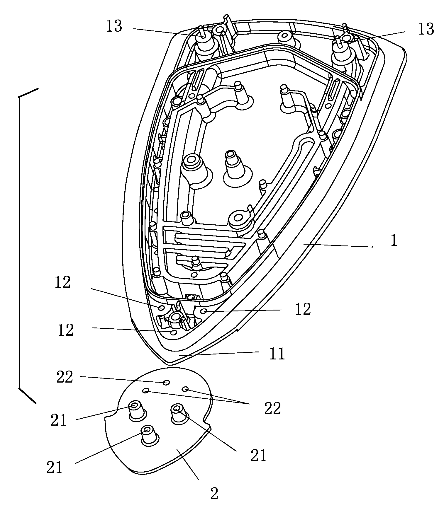
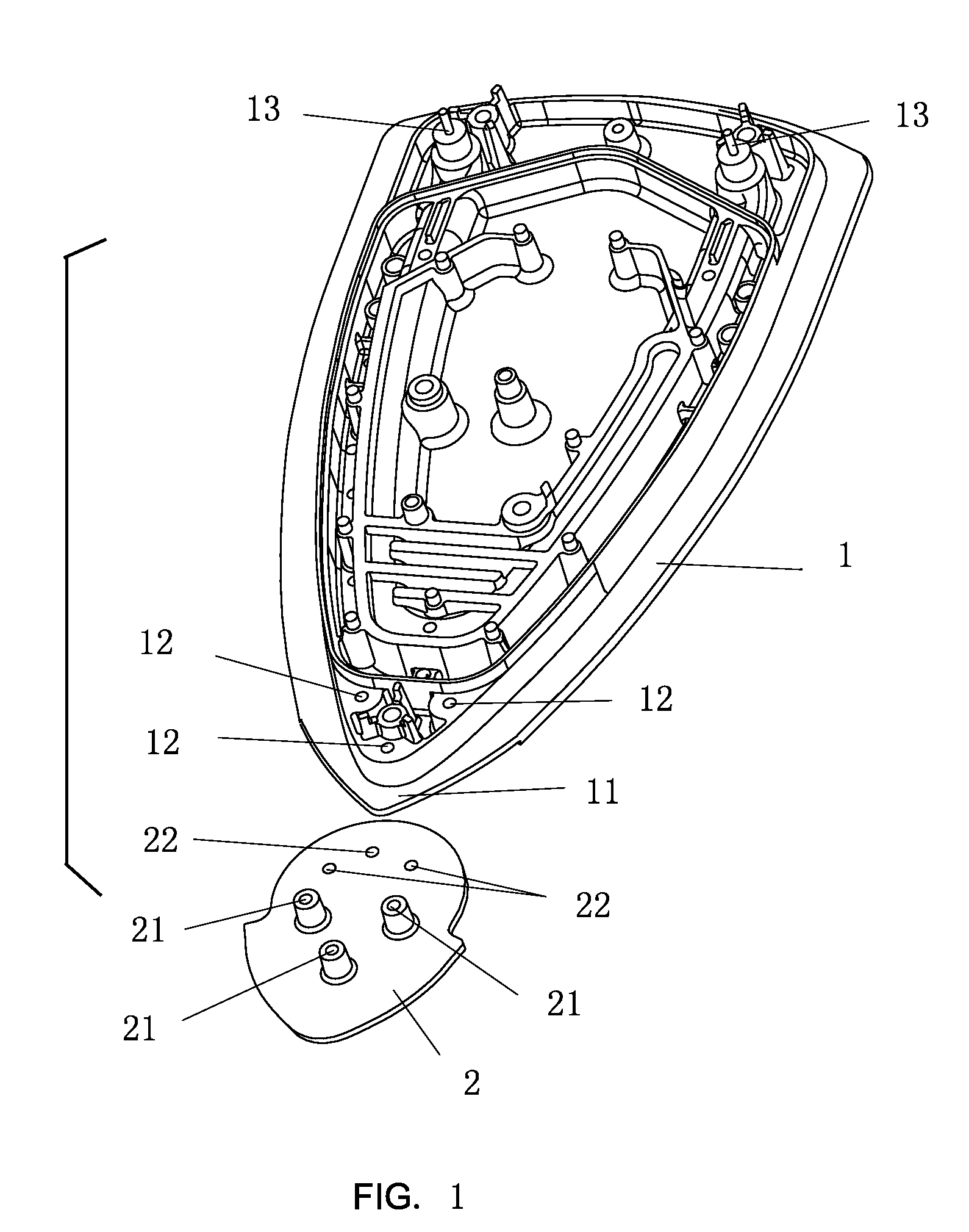
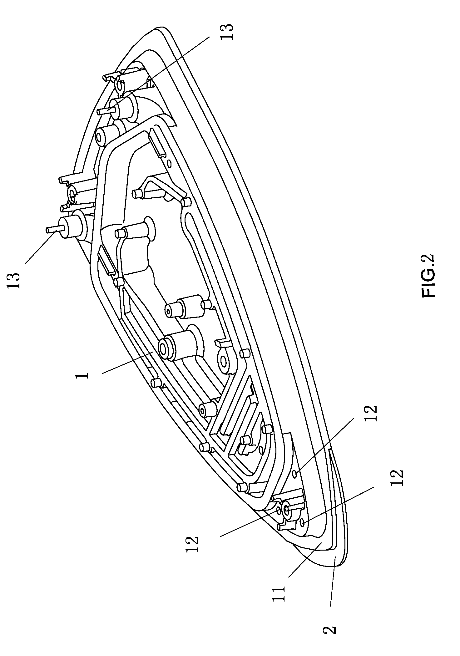
[0017]Referring to FIG. 1, it is the structure of the preferred embodiment based on present utility model. a shallow groove is provided on the bottom surface of the front side 11 of said is soleplate unit 1, a sheet 2, which can be known as decorative plate, is set in said shallow groove.

[0018]Three shaped holes 12 and three screw holes is provided in the front side 11 of said soleplate unit 1, said front side 11 is above said shallow groove. The tubular electric heating element is installed in the said soleplate unit 1, two electrodes 13 of said tubular electric heating element are introduced upwardly from the rear of said soleplate unit 1.

[0019]The shape of said sheet 2 is tongue-shaped, a high rigid surface layer is provided on the surface of said sheet 2 by Anodizing or other process, or said sheet 2 is made of high rigid material. Three short rods 21 having screw hole, which are corresponding to the three shaped holes of the soleplate unit 1, are set on the top surface of the m...

embodiment 2

[0023]Referring to FIG. 4, it is a structure of simplified embodiment based on the present utility model, a V-shaped sheet 120 extends outwardly from the front side 110 of said soleplate unit 100. Two sides of said sheet 120 extend outwardly from the triangle front side 110 of the soleplate unit 100. The tubular electric heating element is installed in the said soleplate unit 100, two electrodes 130 of said tubular electric heating element are introduced upwardly from the rear of said soleplate unit 100.

[0024]Referring to FIG. 5, since the sheet 120 extends outwardly from the bottom surface of said soleplate unit 100, and the bottom surface of said sheet 120 and the bottom surface of said soleplate unit 100 are on same level.

[0025]Since the sheet 120 formed on the front side 110 of soleplate unit 100 of the present embodiment is thin, it is very convenient for users to iron the face fabric near the button and the slide fastener, and achieve satisfactory results


PUM


Abstract

A soleplate unit of electric iron with improved front structure, comprising: a shallow groove provided on the bottom surface of the front side of the soleplate unit, a sheet set in said shallow groove and the front of the sheet extending outwardly from the front side of the soleplate unit. A high rigid surface layer is provided on the surface of the sheet, or the sheet is made of high rigid material. The sheet is tongue in shape, and two front sides of the sheet extend outwardly from the front side of the soleplate unit. The soleplate unit can also be provided with a sheet that extends outwardly from the front of the soleplate unit. It is very convenient for users to iron the face fabric near the button and the slide fastener.

Description

TECHNOLOGY FIELD[0001]The present utility model relates to components of electric iron, especially to the soleplate unit of electric iron with improved front structure.BACKGROUND OF THE INVENTION[0002]The soleplate unit of existing electric iron is thick so as to the tubular electric heating element can be installed in the said soleplate unit. The front of soleplate unit is designed to wedge-shaped triangle , but it is hard to iron the face fabric near the button and the slide fastener.SUMMARY OF THE INVENTION[0003]The present utility model is to provide a soleplate unit of electric iron convenient for ironing the face fabric near the button and the slide fastener.[0004]The present utility model adopts the following technical solution:[0005]The soleplate unit of electric iron comprises: a shallow groove provided on the bottom surface of the front side of said soleplate unit, a sheet set in said shallow groove and the front side of said sheet extending outwardly from the front side o...

Claims


Application Information

Patent Timeline
Patent Type & Authority Applications(United States)
IPC IPC(8): D06F75/38
CPCD06F75/38
Inventor PAN, CHIEN-CHIH
Owner TSANN KUEN ZHANGZHOU ENTERPRISE CO LTD
Learn More