Flexible support apparatus

a support device and flexible technology, applied in the direction of mechanical devices, machine supports, other domestic objects, etc., can solve the problems of not being particularly portable, careful removal and disassembly, and wall damage,

Inactive Publication Date: 2010-06-03
JOSEPH JOHN
View PDF7 Cites 3 Cited by
  • Summary
  • Abstract
  • Description
  • Claims
  • Application Information

AI Technical Summary

Benefits of technology

[0012]Finally, it is a general object of the invention to provide improved elements and arrangements thereof in an apparatus for the purposes described which is inexpensive, dependable and full

Problems solved by technology

While these devices are generally functional they suffer from several drawbacks.
First, they tend to require complicated anchoring systems to support them to the wall or other support surface and thus tend to do some damage to the wall.
Secondly, they are not particularly portab

Method used


Image

  • Flexible support apparatus
  • Flexible support apparatus
  • Flexible support apparatus

Examples


first embodiment

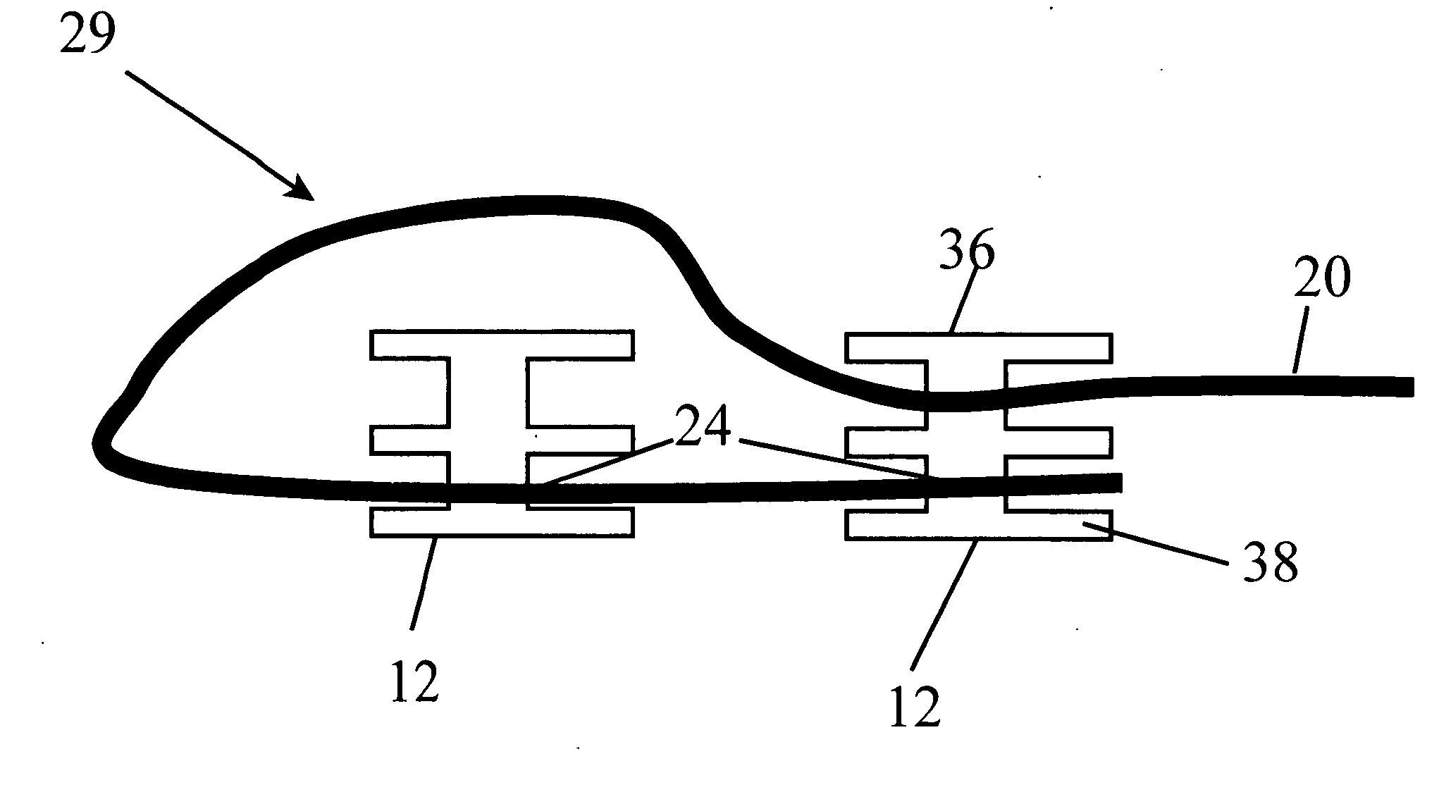
[0027]The anchoring member 12, as shown in FIG. 3A, includes an outer sleeve or portion 31 which is formed of a central post 34 with an axial bore 35 that connects opposing end discs 36, 38 as well as central disc 40, and an inner portion 42 which is a fastener such as a screw or nail. In a first embodiment, end disc 38 and central disc 40 have the same diameter, but end disc 36 has a diameter approximately 25% smaller than discs 38 and 40. The size and number of discs can vary according to function as discussed in more detail below. Also, the discs 36, 38, 40 may be slightly elliptical or any other gem An integral construction may be used to form the outer portion 31 of anchoring member 12, the outer portion 31 preferably being formed of unitary construction, e.g., by molding. Any rigid, durable material may be used to form the anchoring member 12 such as a hardened plastic. The axial bore 35 extends through the anchoring member 12, the bore sized to receive a fastener 42 such as a...

fourth embodiment

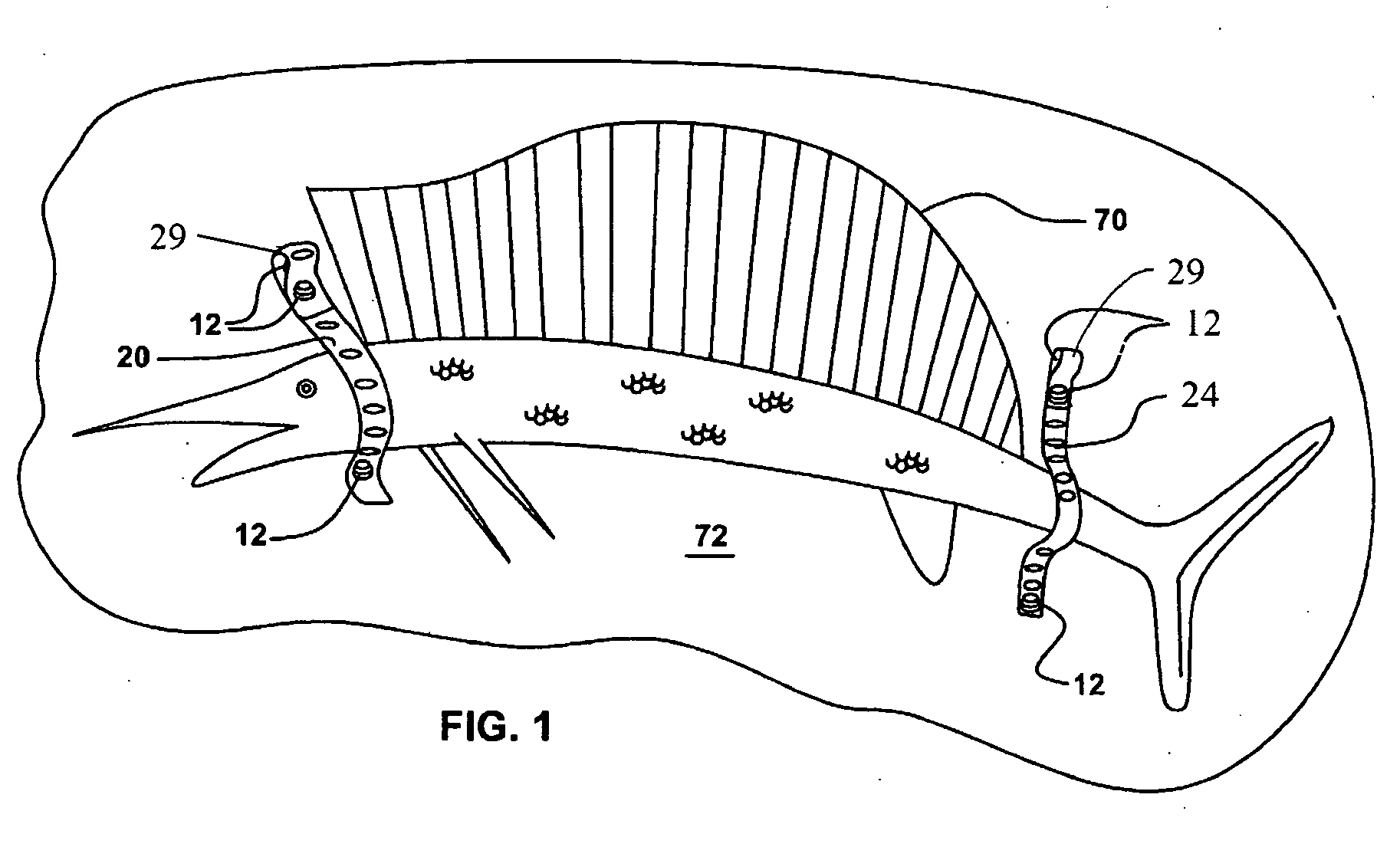
[0031]Also as mentioned above, an anchoring member 112 with only two discs, 138, 140 may be used as shown in FIG. 3C. This embodiment of the anchoring member 112 is expedient when used as a non or limited weight bearing attachment and allows for quick release of the apparatus. Such an anchoring member may be used for example in the place of lowermost anchoring member 112 as shown in FIG. 1. Discs can be all large diameter to increase resistance to accidental disengagement when heavy objects are supported or movement of the supported article is anticipated. An all large diameter disk anchoring member 212 is shown in cross section in FIG. 3B. Member 212 includes an outer sleeve or portion 231 which is formed of a central post 234 with an axial bore 235 that connects opposing end discs 236, 238 as well as central disc 240, and an inner portion 242 which is a fastener such as a screw or nail. the anchoring member 312 is shown in FIG. 3D, and can be seen to have three discs 336, 338, and...


PUM


Abstract

An improved support and closure arrangement includes a flexible strap and one or more locking heads. The flexible strap has a series of spaced apertures formed therein. A first group of apertures extending from one end and extending over at least half of the strap, the first group serving to allow for adjustably forming an overlapped portion of the strap. A second group of apertures extends from an opposing end of the strap. The locking member has a central post terminating at opposing ends with radially extending, axially aligned discs sized for locking engagement with the apertures of the strap. A third axially aligned disc positioned intermediately along the axis of the post and also radially extending therefrom separates the opposing end discs so that apertures on either end of the strap may be selectively and discretely engaged and disengaged from said discs. The locking member includes a central bore adapted to receive a screw or equivalent fastening member. The arrangement is used as a support by overlapping the strap and locking in place a pair of the first apertures to form a loop which functions as a primary anchor for the support, with the locking member serving to secure the loop to a support surface, the end opposite of the loop secured to the support surface at a position most conducive to stable supporting of an object. The locking heads are adaptable for use as anchoring members in a variety of applications.

Description

BACKGROUND OF THE INVENTION[0001]The present invention relates generally to support devices and methods for supporting objects onto vertical surfaces. More particularly, it relates to an improved adjustable support device which can also function as a closure for doors, gates, etc.[0002]Support apparatuses for attaching objects to a vertical surface are known in the art and typically comprise some type of bracket assembly with several rigid support members configured to form the dual functions of vertical support and object retention. While these devices are generally functional they suffer from several drawbacks. First, they tend to require complicated anchoring systems to support them to the wall or other support surface and thus tend to do some damage to the wall. Secondly, they are not particularly portable in that they must be carefully removed and disassembled and are also bulky. Also, they cannot be easily configured to reliably support irregularly shaped objects.[0003]U.S. Pa...

Claims


Application Information

Patent Timeline
IPC IPC(8): A47F5/08
CPCE05C17/36A47G1/16E05C19/184
Inventor JOSEPH, JOHN
Owner JOSEPH JOHN
Why Eureka
Try Eureka