Vehicle lighting device

a technology for vehicle lighting and lighting fixtures, which is applied in semiconductor devices, light sources, transportation and packaging, etc., and can solve the problems of reduced light diffusion, reduced light distribution pattern, and reduced light distribution pattern of vehicle lighting fixtures

Inactive Publication Date: 2010-06-03
HARISON TOSHIBA LIGHTING CORP
View PDF5 Cites 69 Cited by
  • Summary
  • Abstract
  • Description
  • Claims
  • Application Information

AI Technical Summary

Benefits of technology

[0010]A vehicle lighting device according to the present invention includes a light source whose optical axis is set in a horizontal direction, and an optical member configured to control emitted light from the light source, wherein the optical member includes: a lens section provided on the optical axis of the light source and configured to emit incident light from the light source by changing the incident light by refraction; an upper reflector section integrated with the lens section and made of a light transmissive material, and configured to emit incident light from the light source by totally reflecting the incident light at an upper reflection surface formed above the lens section; and a

Problems solved by technology

In the technique disclosed in Japanese Patent Application Laid-Open Publication No. 2006-164923, however, the illumination pattern may have lower sharpness since the desired light distribution is achieved by offsetting the light source from an ideal position thereof with respect to each functional section of the prism lens.
The phenomenon is believed to occur because light diffused over a wide angle in a longitudinal direction from the LED cannot be sufficiently controlled by the prism lens.
When the both end portions of the illumination pattern expand in the upward and downward direction, the light distribution pattern required in the vehicle lighting fixture may not be achieved, or visibility may be deteriorated due to unnecessary light especially by the expansion in the upward direction.

Method used


Image

  • Vehicle lighting device
  • Vehicle lighting device
  • Vehicle lighting device

Examples


first embodiment

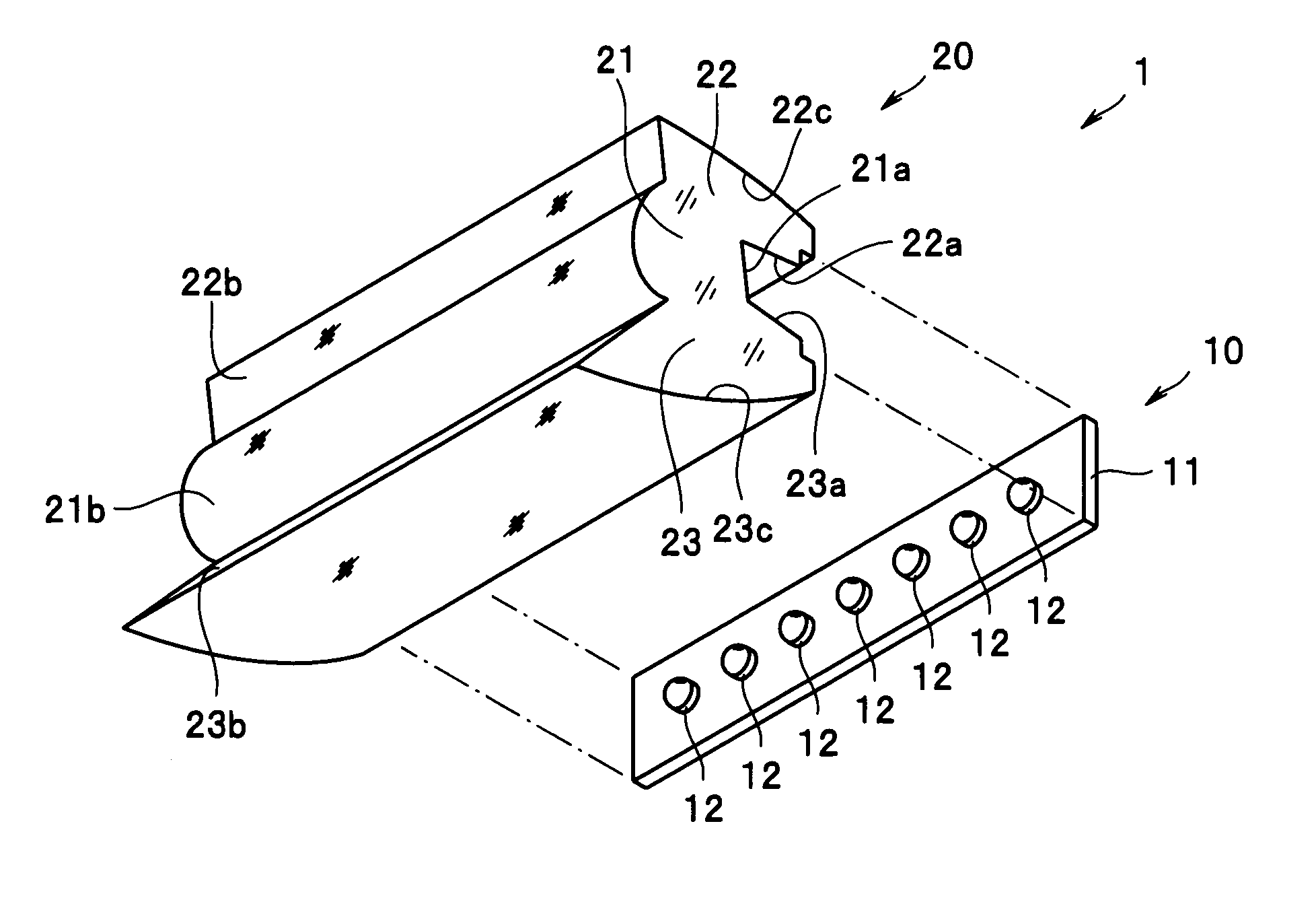
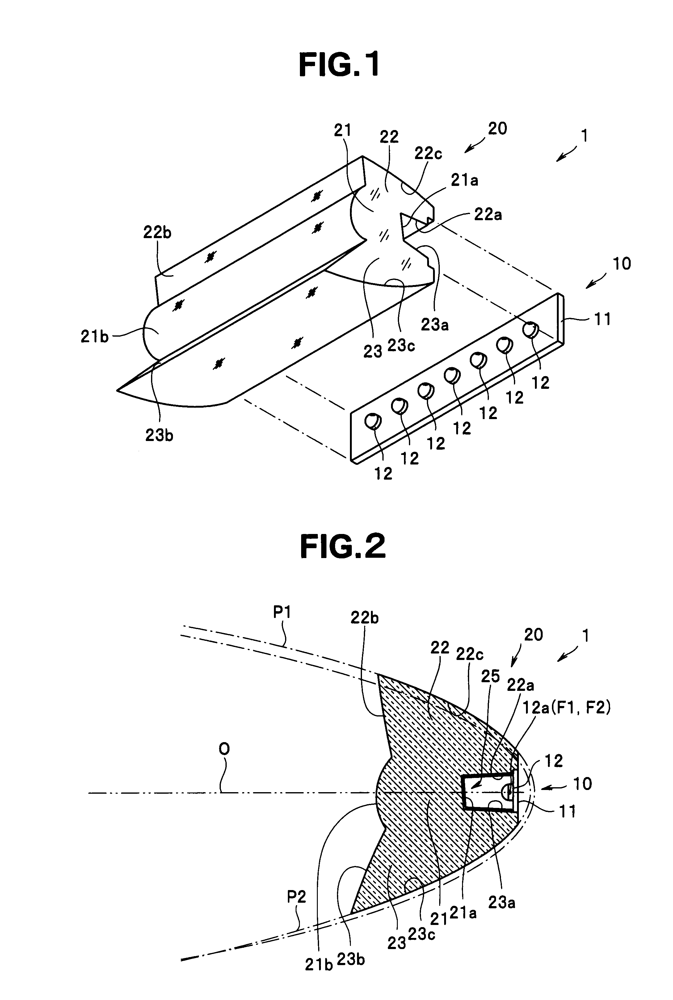
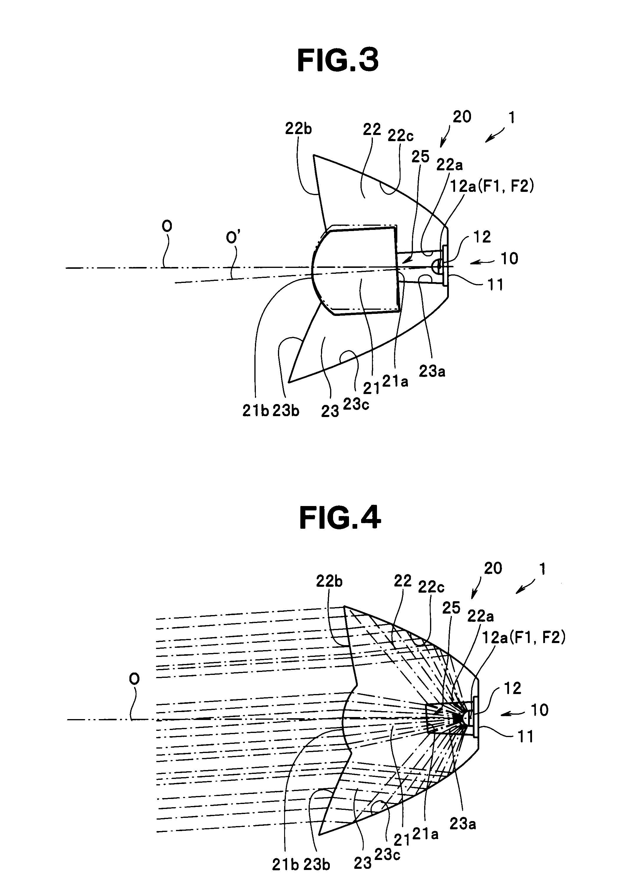
[0034]In the following, embodiments of the present invention will be described with reference to the drawings. FIGS. 1 to 5 are related to the present invention. FIG. 1 is an exploded perspective view schematically illustrating a configuration of a vehicle lighting device. FIG. 2 is a vertical sectional view illustrating a portion of the vehicle lighting device. FIG. 3 is an explanatory view illustrating an optical axis of a lens section. FIG. 4 is an explanatory view illustrating a simulation result of behavior of light that enters an optical member. FIG. 5 is an explanatory view illustrating an illumination pattern when the optical member according to the present invention is used.

[0035]In FIGS. 1 and 2, reference numeral 1 denotes a vehicle lighting device, and in the present embodiment, specifically denotes a vehicle fog lamp. The lighting device 1 includes a light source unit 10 having a plurality of light emitting diodes (LEDs) 12 as a light source, and an optical member 20 co...

second embodiment

[0063]With the present embodiment, substantially same effects as those of the aforementioned second embodiment can be achieved. In this case, since the light radiated at a wide angle in the horizontal direction from each of the LEDs 12 to enter the lower portion of the incident surface 121a can be effectively emitted as the illumination light from the emission surface 221b without being guided to outside the illumination light path, light use efficiency can be improved.

[0064]The refraction section 130 described in the aforementioned second embodiment and the emission surface 221b described in the aforementioned third embodiment may be combined to constitute the lens section 121 as shown in FIG. 18, for example. With the configuration, an illumination pattern of desired light distribution required in a fog lamp or the like can be more appropriately projected.

[0065]Although the example in which the present invention is applied to the fog lamp is described in the aforementioned respect...


PUM


Abstract

An optical axis O′ of a lens section of an optical member is inclined downward relative to a horizontal direction (an optical axis O of each LED) from a light emitting section of each LED. Therefore, an area at and below a horizontal position of a lighting device is illuminated by the lens section while each LED is arranged at an optically ideal position relative to the lens section. Also, reflection surfaces of upper and lower reflector sections and of the optical member are respectively set based on parabolas P1 and P2 different from each other with focal points F1 and F2 positioned at each LED. Therefore, the area at and below the horizontal position of the lighting device is illuminated respectively by the reflector sections while each LED is arranged at an optically ideal position relative to the reflector sections.

Description

CROSS-REFERENCE TO RELATED APPLICATIONS[0001]This application is based upon and claims the benefit of priority from the prior Japanese Patent Application No. 2008-307886 filed in Japan on Dec. 2, 2008 and Japanese Patent Application No. 2009-055378 filed in Japan on Mar. 9, 2009; the entire contents of which are incorporated herein by reference.BACKGROUND OF THE INVENTION[0002]1. Field of the Invention[0003]The present invention relates to a vehicle lighting device configured to illuminate a preset illumination area with predetermined light distribution.[0004]2. Description of Related Art[0005]Light emitting diodes (LEDs) typically have an advantage that the LEDs consume less electricity and have a long operating life. In recent years, as LEDs have higher output, LEDs are expected to be applied as a light source of a lighting device, such as a headlamp and fog lamp mounted on a vehicle, in which a higher light intensity is required, for example.[0006]Meanwhile, in the vehicle lighti...

Claims


Application Information

Patent Timeline
IPC IPC(8): B60Q1/04B60Q1/00
CPCF21S48/1154F21S48/125F21Y2103/003F21Y2101/02F21S48/1329F21Y2103/10F21Y2115/10F21S41/143F21S41/151F21S41/25F21S41/322
Inventor MATSUBA, YOSHIAKIWAGATSUMA, YUJIKATO, TAKEO
Owner HARISON TOSHIBA LIGHTING CORP
Why Eureka
Try Eureka