Toner conveyance device and image forming apparatus incorporating same

a technology of toner conveyance and image forming apparatus, which is applied in the direction of electrographic process apparatus, instruments, optics, etc., can solve the problems of clogging toner may build up inside the toner conveyance path,

Inactive Publication Date: 2010-06-10
RICOH KK
View PDF3 Cites 37 Cited by
  • Summary
  • Abstract
  • Description
  • Claims
  • Application Information

AI Technical Summary

Benefits of technology

[0012]The protrusion includes a basal portion, a convex portion, and a protrusion front edge surface. The basal portion is continuous with and adjacent and connected to the body. The basal portion has a first width greater than a helical pitch of the helical blade of the conveyance member in the axial direction of the conveyance member. The convex portion protrudes from the basal portion and has a second width smaller than the helical pitch of the helical blade

Problems solved by technology

However, in such toner conveyance device, the toner may build up

Method used


Image

  • Toner conveyance device and image forming apparatus incorporating same
  • Toner conveyance device and image forming apparatus incorporating same
  • Toner conveyance device and image forming apparatus incorporating same

Examples


Embodiment Construction

[0035]In describing exemplary embodiments illustrated in the drawings, specific terminology is employed for the sake of clarity. However, the disclosure of this specification is not intended to be limited to the specific terminology so selected and it is to be understood that each specific element includes all technical equivalents that operate in a similar manner.

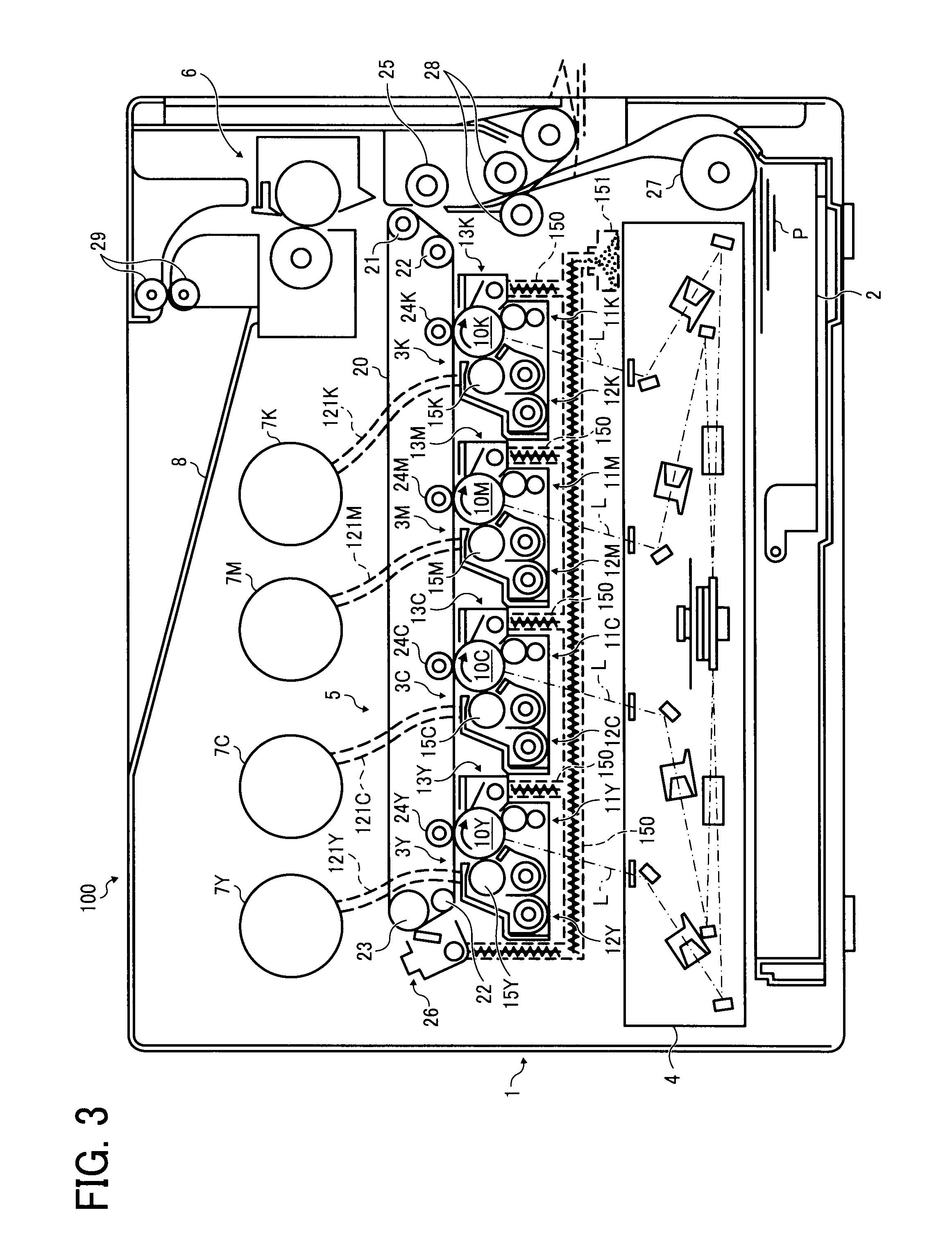
[0036]Referring now to the drawings, wherein like reference numerals designate identical or corresponding parts throughout the several views, in particular to FIG. 3, an image forming apparatus 100 according to an exemplary embodiment of the present invention is explained.

[0037]FIG. 3 is a schematic view of the image forming apparatus 100. As illustrated in FIG. 3, the image forming apparatus 100 includes a body 1, a paper tray 2, an output tray 8, and a feed roller 27.

[0038]The body 1 includes image forming stations 3Y, 3C, 3M, and 3K, an optical unit 4, an intermediate transfer unit 5, a fixing device 6, toner bottles 7Y...


PUM


Abstract

In a toner conveyance device, a first agitator contacts a helical outer circumferential surface of a blade of a conveyance member for conveying toner, and swings in coordination with rotation of the conveyance member to agitate the toner. The first agitator includes a body for bending and swinging in a bending direction perpendicular to an axial direction of the conveyance member, and a protrusion for protruding from the body in a protrusion direction opposite the bending direction of the body. The protrusion includes a basal portion adjacent to the body, a convex portion protruding from the basal portion, and a protrusion front edge surface having a distance from the body changing in a toner conveyance direction, and contacts the helical outer circumferential surface of the helical blade of the conveyance member.

Description

CROSS-REFERENCE TO RELATED APPLICATION[0001]The present application is based on and claims priority to Japanese Patent Application Nos. 2008-311388, filed on Dec. 5, 2008, and 2009-065802, filed on Mar. 18, 2009, in the Japan Patent Office, each of which is hereby incorporated herein by reference in its entirety.BACKGROUND OF THE INVENTION[0002]1. Field of the Invention[0003]Exemplary aspects of the present invention relate to a toner conveyance device and an image forming apparatus, and more particularly, to a toner conveyance device for conveying toner and an image forming apparatus including the toner conveyance device.[0004]2. Description of the Related Art[0005]Related-art image forming apparatuses, such as copiers, facsimile machines, printers, or multifunction printers having at least one of copying, printing, scanning, and facsimile functions, typically form an image on a recording medium (e.g., a transfer sheet) according to image data. Thus, for example, a charger uniforml...

Claims


Application Information

Patent Timeline
IPC IPC(8): G03G21/00
CPCG03G21/007G03G21/105G03G2215/0802
Inventor TAWADA, TAKAAKI
Owner RICOH KK
Why Eureka
Try Eureka