Oil Pan

a technology of oil pans and oil cylinders, applied in the direction of auxilary lubrication, machines/engines, mechanical equipment, etc., can solve the problems of increasing cost and complexity, increasing the service life of engines, and increasing the chance of leakag

Inactive Publication Date: 2010-06-17
INT ENGINE INTPROP CO LLC
View PDF14 Cites 13 Cited by
  • Summary
  • Abstract
  • Description
  • Claims
  • Application Information

AI Technical Summary

Problems solved by technology

Assembly of multiple components adds to a cycle time in assembly of an engine, increases cost and complexity, and may present opportunity for leakage during the service life of an engine.
Moreover, typical oil pan assemblies may be prone to failure

Method used


Image

  • Oil Pan
  • Oil Pan
  • Oil Pan

Examples


Embodiment Construction

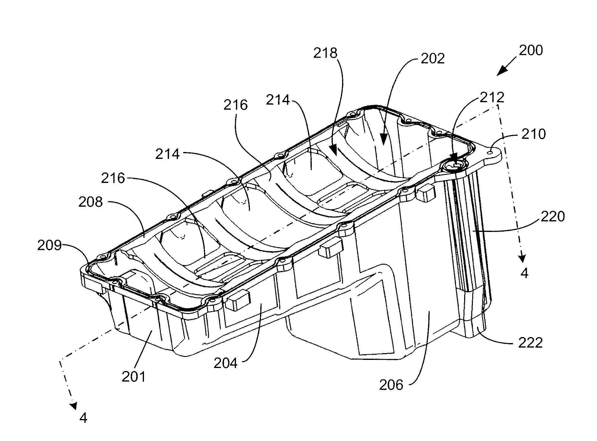
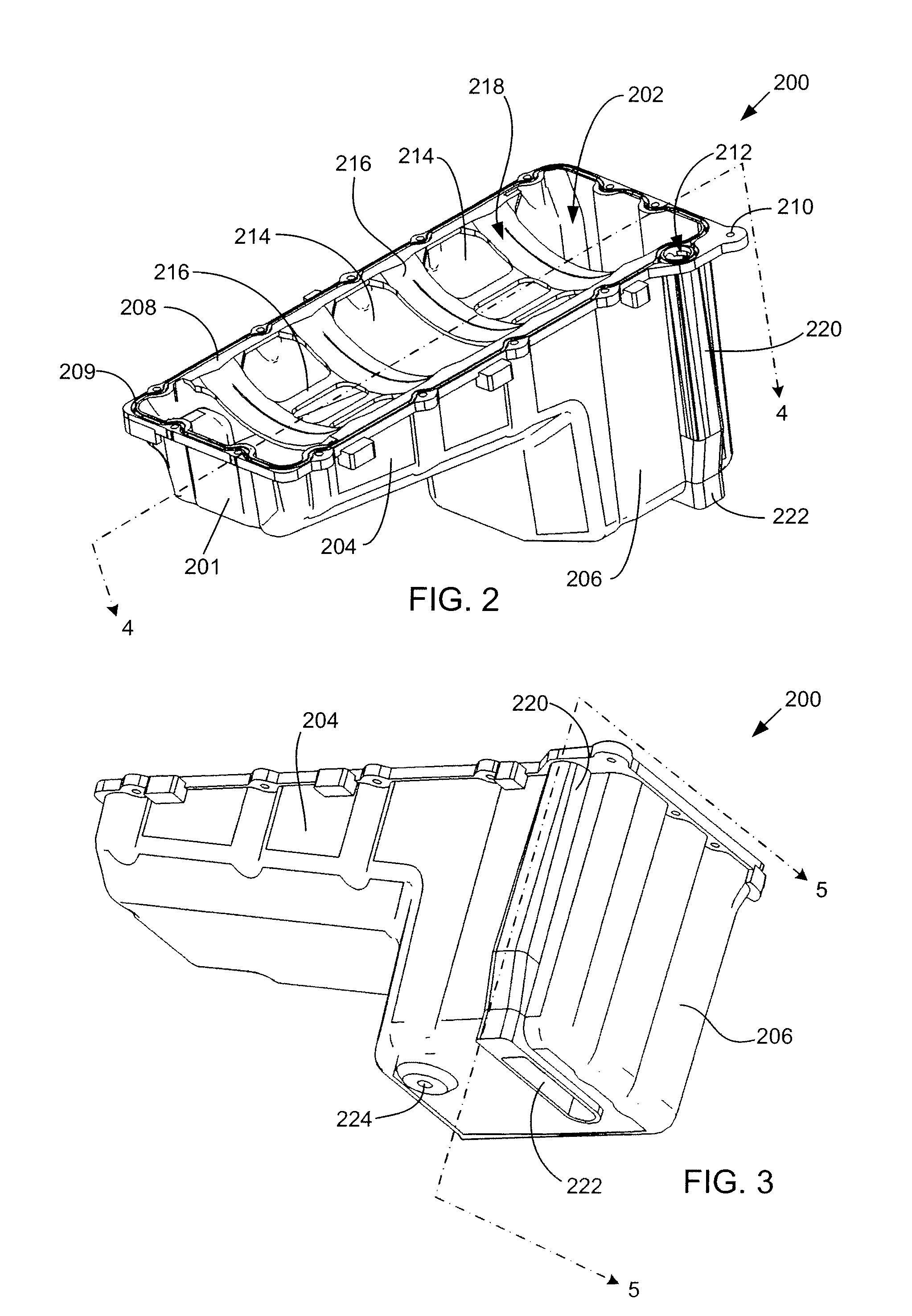
[0013]The following describes an integrated oil pan for an internal combustion engine.

[0014]In one embodiment, the integrated oil pan is a single piece that incorporates the functions of a lower oil pan, an upper oil pan, and an oil pick-up or suction tube. The integrated oil pan may have superior resistance to leakage and failure, be less costly and easier to install when compared to traditional oil pan assemblies.

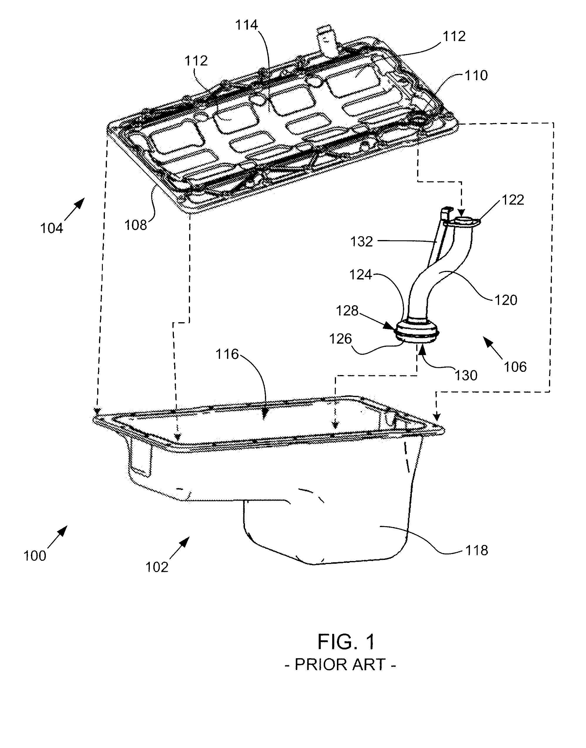
[0015]A prior art oil pan assembly 100 is shown in exploded view in FIG. 1. The oil pan assembly 100 includes a lower oil pan 102, an upper oil pan 104, and a pick-up tube 106. When the oil pan assembly 100 is assembled as shown in FIG. 1, the upper pan 104 is connected to the lower pan 102 along a peripheral sealing surface 108. The pick-up tube 106 is connected to the upper pan 108 at a pass-through opening 110 that is sealed to allow oil that is drawn from the lower pan 102 by the pick-up tube 106 to enter the engine (not shown).

[0016]The upper pan 104 advantageously i...


PUM


Abstract

An oil pan (200) for an internal combustion engine includes a body (201) that defines a reservoir cavity (202). A collector cavity (222) is defined by at least one wall of the body (201) and is in fluid communication with the reservoir cavity (202). An oil supply passage (220) is defined by at least one wall of the body (201) and is in fluid communication with the collector cavity (222).

Description

FIELD OF THE INVENTION[0001]This invention relates to oil pans. More particularly, this invention relates to oil pans for internal combustion engines.BACKGROUND OF THE INVENTION[0002]Internal combustion engines include crankcases having a plurality of cylinders. The cylinders contain pistons whose reciprocating motion caused by combustion events are transferred through a crankshaft to yield a torque output of the engine. Often, engine crankcases are made of cast metal and include passages integrally formed therein for the transfer of various fluids from one location of the engine to another. Fluids typically transferred through passages in an engine include coolant, air, fuel, oil, and so forth.[0003]Engines typically use oil for lubrication and / or actuation of various engine components. A typical engine may contain a considerable amount of oil that circulates therethrough during operation of the engine, and that collects in a reservoir when the engine is not operating. The reservoi...

Claims


Application Information

Patent Timeline
IPC IPC(8): F01M11/06F01M11/00
CPCF01M11/0004F01M2011/0066F01M2011/005F01M2011/0037
Inventor BURKE, NICHOLAS E.VINCER, TYLER R.
Owner INT ENGINE INTPROP CO LLC
Why Eureka
Try Eureka