Floor tool for a cleaning appliance

a technology for cleaning appliances and floor tools, applied in the field of floor tools, can solve problems such as difficulty in manoeuvring floor tools in directions that are not straight lines, and achieve the effect of improving the service life and reducing the difficulty of manoeuvring the floor tools

Active Publication Date: 2010-06-24
DYSON TECH LTD
View PDF27 Cites 91 Cited by
  • Summary
  • Abstract
  • Description
  • Claims
  • Application Information

AI Technical Summary

Benefits of technology

[0009]By including a bend in the conduit, movement of the floor tool beyond that of a straight line is made possible by rotating the free end of the conduit. To facilitate steering of the floor tool, the conduit preferably comprises a forward portion that is pivotally attached to a rearward portion. The wheels are then rotatably attached to the forward portion, which is in turn rotatably attached to the cleaner head. This arrangement additionally helps to prevent the cleaner head being inadvertently lifted as the floor tool is manoeuvred over the cleaning surface. Advantageously, the rearward portion is attached to the forward portion at points above those at which the wheels are attached to the forward portion. Consequently, the length of the conduit may be kept to a minimum, resulting in a more compact floor tool.
[0011]The surfaces of the wheels are preferably coincident with a common sphere. Moreover, the centre of the common sphere is ideally coincident with the longitudinal axis of the conduit. Consequently, as the conduit rotates relative to the cleaner head, the conduit maintains the same height above the cleaning surface. This then helps prevent lifting of the cleaner head as the floor tool is steered in different directions.

Problems solved by technology

However, there is often difficultly in manoeuvring the floor tool in directions beyond that of a straight line.

Method used


Image

  • Floor tool for a cleaning appliance
  • Floor tool for a cleaning appliance
  • Floor tool for a cleaning appliance

Examples


Embodiment Construction

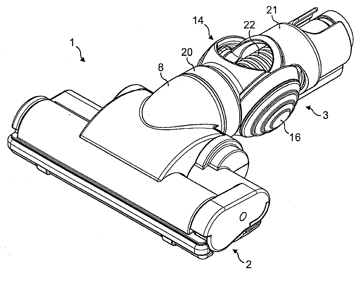
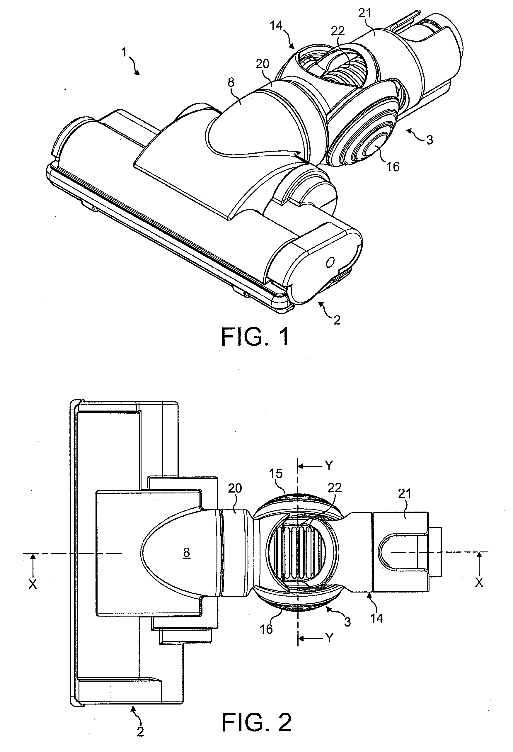
[0018]The floor tool 1 of FIGS. 1 to 4 comprises a cleaner head 2 rotatably attached to a coupling 3. The free end of the coupling 3 is attachable to a wand, hose or other such duct of a cleaning appliance (not shown).

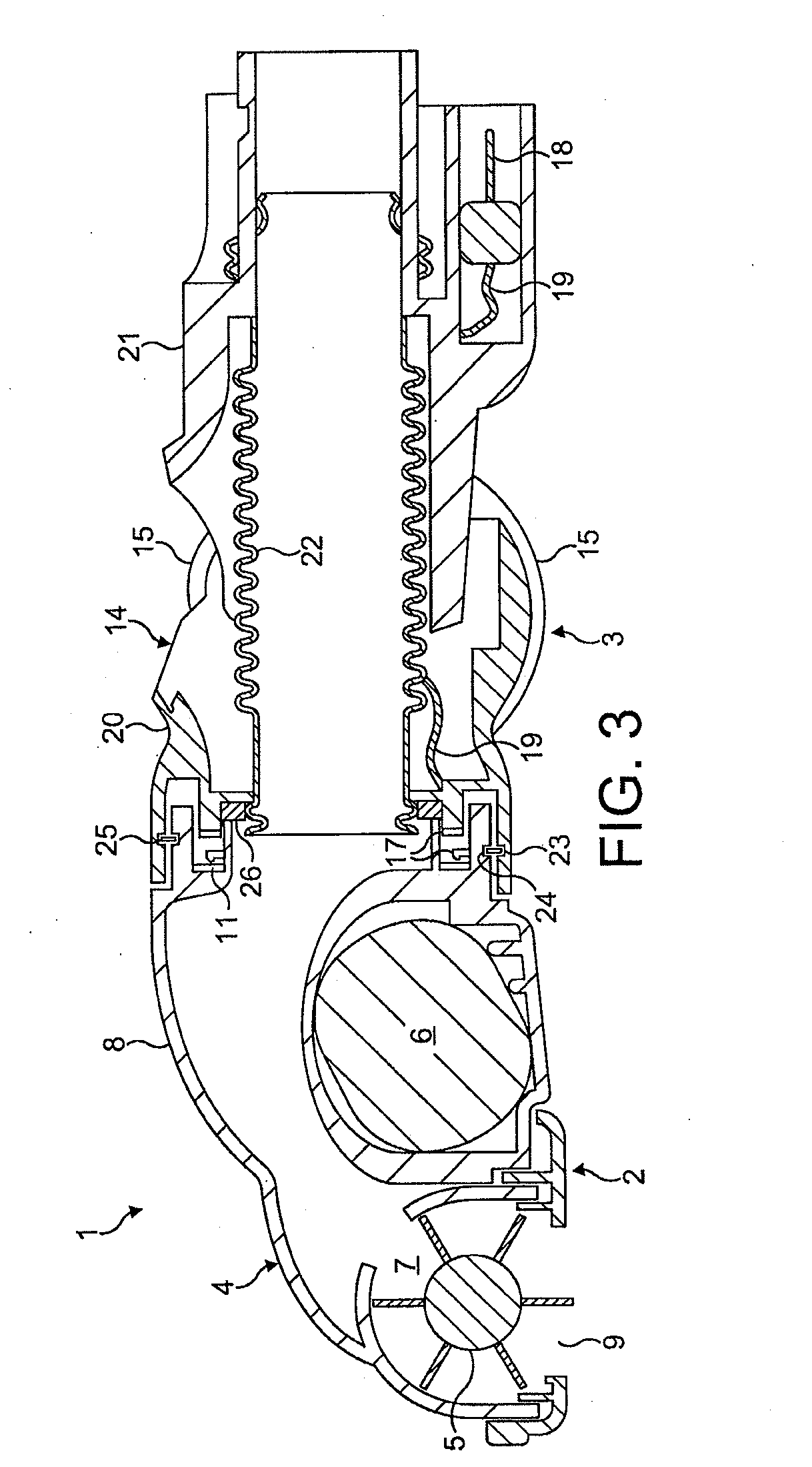
[0019]The cleaner head 2 comprises a housing 4, a brushbar 5 and a motor 6. The housing 4 defines a chamber 7 within which the brushbar 5 is rotatably mounted, and an outlet duct 8 that extends from the chamber 7 to the rear of the cleaner head 2. An opening 9 formed on the underside of the housing 2 provides an inlet to the chamber 7. The brushbar 5 is driven by the motor 6, which is located to the rear of the cleaner head 2 beneath the outlet duct 8. The motor 6 is coupled to an electrical terminal 11 provided at an end of the outlet duct 8, through which electrical power may be delivered to the motor 6.

[0020]The coupling 3 comprises a conduit 14 carried by a pair of wheels 15,16, an electrical terminal 17,18 provided at each end of the conduit 14, and an electrical ...


PUM


Abstract

A floor tool for a cleaning appliance including a cleaner head rotatably attached to a conduit carried by a pair of wheels that converge beneath the conduit.

Description

REFERENCE TO RELATED APPLICATIONS[0001]This application claims the priority of United Kingdom Application No. 0823191.2, filed Dec. 19, 2008, the entire contents of which are incorporated herein by reference.FIELD OF THE INVENTION[0002]The present invention relates to a floor tool for a cleaning appliance.BACKGROUND OF THE INVENTION[0003]Cleaning appliances, such as vacuum cleaners, floor polishers and shampoo machines, may include a hose-and-wand assembly to which different accessories may be attached. One such accessory is a floor tool which a user manoeuvres back and forth over a surface to be cleaned. The floor tool may include wheels which aid the user in manoeuvring the floor tool. However, there is often difficultly in manoeuvring the floor tool in directions beyond that of a straight line.SUMMARY OF THE INVENTION[0004]In a first aspect, the present invention provides a floor tool for a cleaning appliance comprising a cleaner head rotatably attached to a conduit carried by a ...

Claims


Application Information

Patent Timeline
Patent Type & Authority Applications(United States)
IPC IPC(8): A46B13/00
CPCA47L9/02A47L9/009
Inventor MCLEOD, DAVID ANDREW
Owner DYSON TECH LTD
Why Eureka
Try Eureka