Pneumatic tire

Inactive Publication Date: 2010-06-24
GEOR FRANCOIS PIERRE CHARLES GERARD +4
View PDF21 Cites 4 Cited by
  • Summary
  • Abstract
  • Description
  • Claims
  • Application Information

AI Technical Summary

Benefits of technology

[0013]“Chafers” refer to narrow strips of material placed around the outside of the bead to protect cord plies from the rim, distribute flexing above the rim, and to seal the tire.

Problems solved by technology

The disadvantage to zigzag belt layers is that at the edges near the shoulder, there are overlapping layers.

Method used


Image

  • Pneumatic tire
  • Pneumatic tire
  • Pneumatic tire

Examples


Embodiment Construction

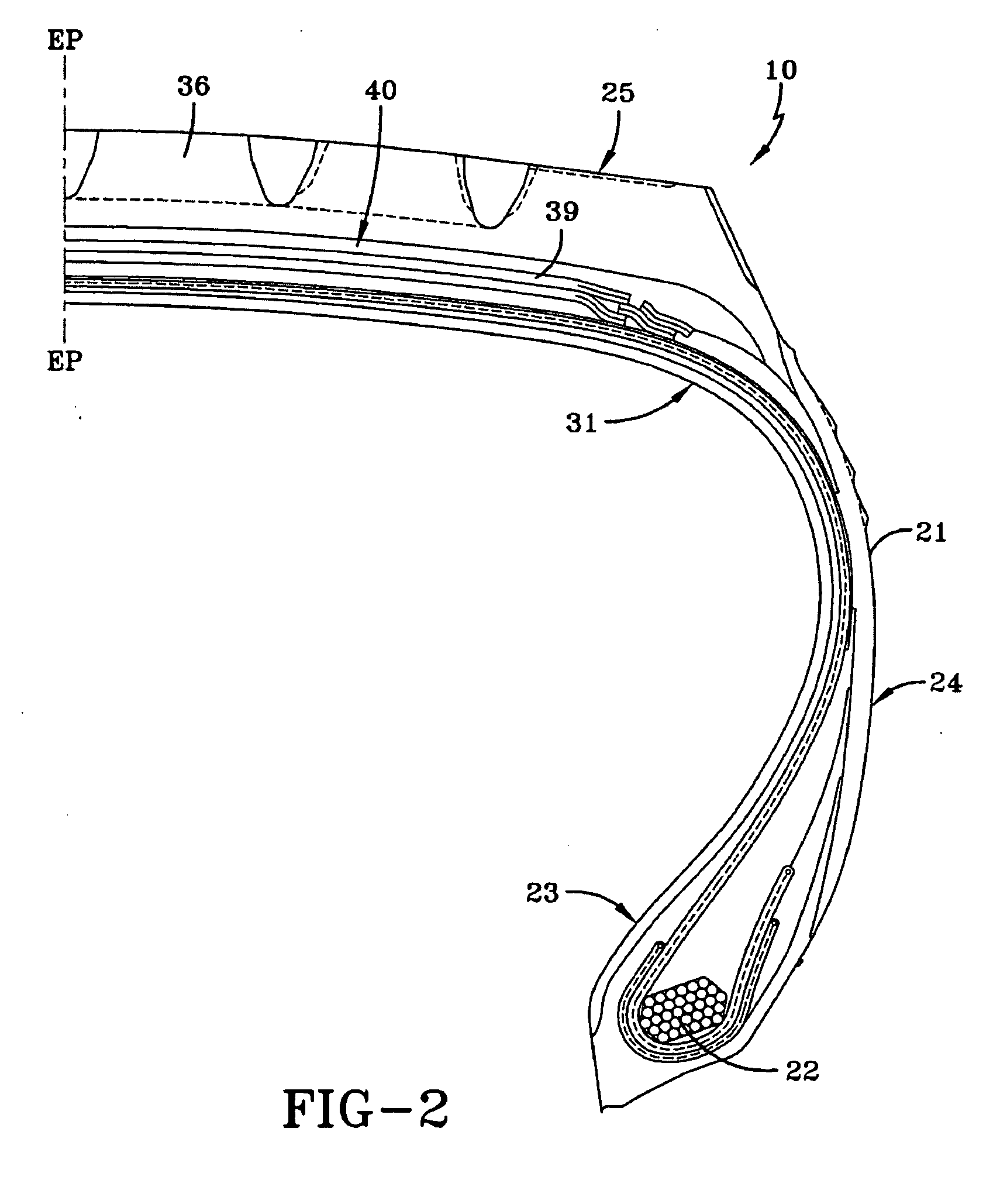
[0039]FIG. 2 illustrates a partial cross-section of an exemplary radial tire 10 which includes a bead portion 23 having a bead core 22 embedded therein, a sidewall portion 24 extending radially outward from the bead portion 23, and a cylindrical tread portion 25 extending between radially outer ends of the sidewall portions 24. The tire 10 is reinforced by a carcass 31 toroidally extending from one bead portion 23 to the other bead portion 23′ (not shown). The carcass 31 may include at least one carcass ply 32. The carcass ply 32 is anchored to the bead core and for example, may wind around each bead core 22 from inside of the tire 10 away from the equatorial plane EP to form turnup portions. A belt structure 40 is arranged between the carcass 31 and the tread portion 25.

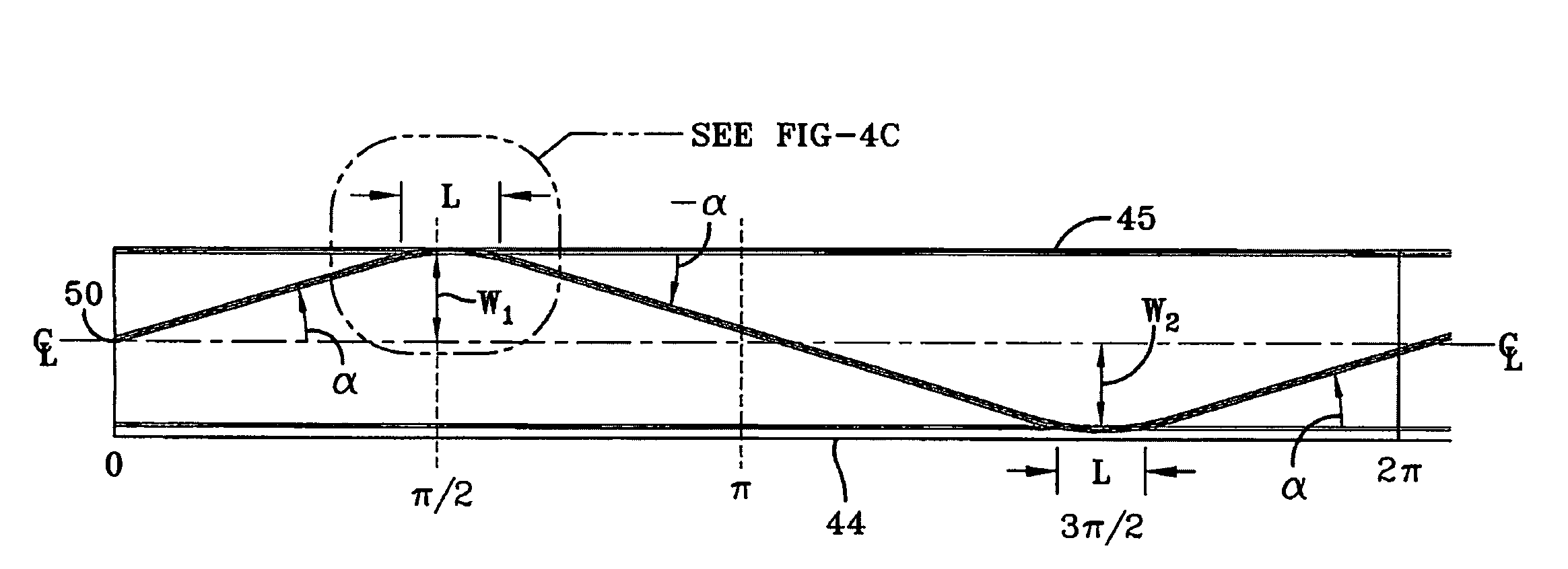
[0040]The belt structure 40, according to an example embodiment of the present invention, comprises one or more belts, wherein at least one belt is a new and improved zigzag belt structure 39. The zigzag belt struct...


PUM


Abstract

A pneumatic tire comprising a tread, a carcass and a zigzag belt structure interposed between the carcass and the tread is provided. The zigzag belt structure is formed of at least two layers of cords interwoven together from a strip of rubber reinforced with one or more cords, wherein the strip forming the zigzag belt structure is layed up in a first zigzag winding extending from a first lateral belt edge to a second lateral belt edge in a zigzag wavelength having a first amplitude W1 followed by a second amplitude W2, and a second zigzag winding formed of a zigzag wavelength having a first amplitude W2 followed by a second amplitude W1.

Description

FIELD OF THE INVENTION[0001]This invention relates to a pneumatic tire having a carcass and a belt reinforcing structure, and, more particularly, to radial ply tires for use in aircraft, trucks and other high load applications.BACKGROUND OF THE INVENTION[0002]In tires that have heavy loads such as truck tires or aircraft tires, zigzag belt layers have been utilized for the belt package. Zigzag belt layers eliminate working belt endings at the shoulder. An exemplary portion of a tire with a zigzag belt layer 5 is shown in FIG. 1. The advantage of zigzag belt layers is that there are no working belt edges near the shoulder, which greatly improves tire durability. The disadvantage to zigzag belt layers is that at the edges near the shoulder, there are overlapping layers. In some areas there are too many layers, such as 4 or more layers typically, and even 6 or more layers in some locations. The reduction of overlapping strips in the shoulder area has been shown to improve durability. T...

Claims


Application Information

Patent Timeline
IPC IPC(8): B60C9/00
CPCB60C9/263B60C2200/02B60C2200/06Y10T152/10783
Inventor GEORGES, FRANCOIS PIERRE CHARLES GERARDGILLARD, JEAN-MICHEL ALPHONSE FERNANDKRIER, ROLAND WILLIBRORDMATHONET, VINCENT BENOITNICOLAS, BERNARD ROBERT
Owner GEOR FRANCOIS PIERRE CHARLES GERARD
Why Eureka
Try Eureka