
Spatial and temporal de-interlacing with error criterion

a spatial deinterlacing and error criterion technology, applied in the field of spatial and temporal deinterlacing with error criterion, can solve the problems of insufficient quality level for the near future of video and digital video demands, no means to calculate the reliability of a directional interpolation, and relatively high memory requirements for spatial deinterlacers

Inactive Publication Date: 2010-06-24
DYNAMIC DATA TECH LLC
View PDF7 Cites 25 Cited by
  • Summary
  • Abstract
  • Description
  • Claims
  • Application Information

AI Technical Summary

Benefits of technology

[0009]Furthermore, a method of calculating a reliability of a directional interpolation is provided wherein, one embodiment includes using the reliability of both the directional and vertical interpolation to determine a mix factor between the directional and vertical interpolation results. Furthermore, both the information along and perpendicular to a detected dominant edge may be used. An exemplary method further may al

Problems solved by technology

Although EDDI exceeds the quality level of many other spatial de-interlacers, its quality level is insufficient for the video and digital video demands of the near future.
Moreover, the complexity and memory requirements are relatively high for spatial de-interlacers.
Furthermore, some general ideas for a new type of directional de-interlacer are presented in the preceding papers, but at present there is no means to calculate the reliability of a directional interpolation.
Moreover, the algorithms rely heavily on a single error criterion.

Method used


Image

  • Spatial and temporal de-interlacing with error criterion
  • Spatial and temporal de-interlacing with error criterion
  • Spatial and temporal de-interlacing with error criterion

Examples


Embodiment Construction

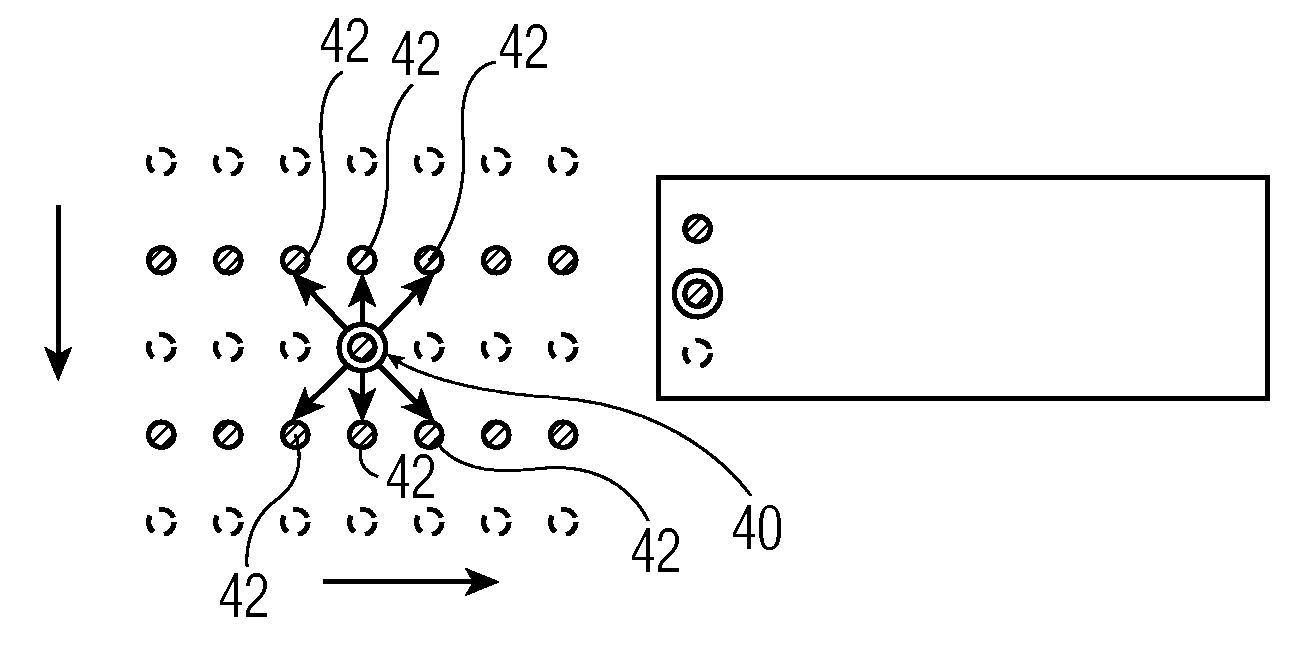
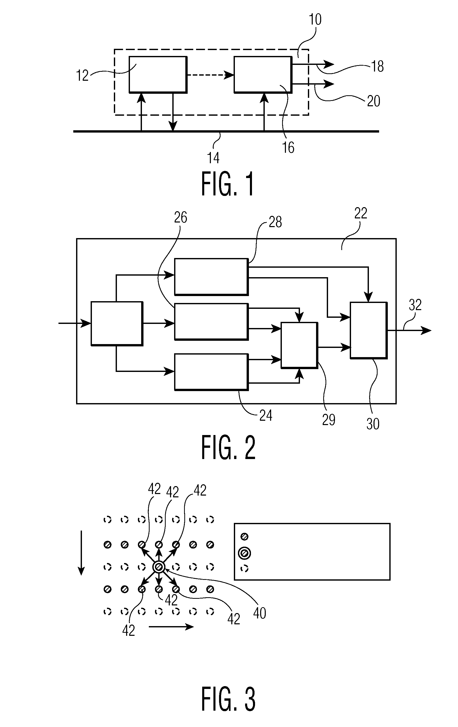
[0025]A Memory-Based Video Processor (MBVP) is considered a successor of the Memory Based Scaler (MBS). As the name suggests, the MBVP can interface via memory, although direct streaming is a possibility also. An exemplary Video pipe 10 that incorporates an exemplary MBVP device 12 is shown in FIG. 1. The MBVP device 12 interfaces a memory bus 14 and provides an input to a CPIPE (composition pipe) 16. A CPIPE 16 processes the inputs and processes the outputs(s) 18, 20.

[0026]An exemplary MBVP device 12 comprises various components of which a de-interlacer is one. An exemplary de-interlacer block diagram 22 is shown in FIG. 2. The MBVP de-interlacer 22 comprises a spatial de-interlacer, a temporal de-interlacer 26, a film / still detector 28 and some mixers 29, 30.

[0027]The first mixer 29 basically mixes the output of the temporal de-interlacer 26 and the spatial de-interlacer (EDDI+) 24 on a pixel basis. In order to do so, error criterions are used. These error criterions form a measur...


PUM


Abstract

A de-interlacing device and method are provided that may be used in a memory based video processor. The de-interlacer mixes the output of a temporal de-interlacer and a spatial de-interlacer. Two separate error values are used; one for the temporal de-interlacer and another for the spatial de-interlacer. The de-interlacing device calculates from the two error values, using a non-linear mapping, a mix factor used to mix between the outputs of the spatial and temporal de-interlacers.

Description

BACKGROUND OF THE INVENTION[0001]Many de-interlacing methods have been published in literature and / or are being commercially used in various products. Methods range from simple spatial de-interlacers to motion-compensated de-interlacers.[0002]The category of spatial de-interlacers, however, is important, as it is often used as a kind of fall-back in case the motion vectors used in the interlacing processes are unreliable, but moreover, it is the category of de-interlacers relied on in low-cost systems. Overviews of de-interlacers (including spatial ones) can be found in G. de Haan and E. B. Bellers, ‘De-interlacing—An overview’, The proceedings of the IEEE, vol. 86, no. 9, pp. 1839-1857, September 1998 and E. B. Bellers and G. de Haan, ‘De-interlacing—A key technology for Scan Rate Conversion’, Advances in Image Communications, Vol. 9, ISBN 0-444-50594-6, Elsevier Science B. V., 2000. Another spatial de-interlacer that is not included in the References above can be found in G. de Ha...

Claims


Application Information

Patent Timeline
IPC IPC(8): H04N7/01
CPCH04N7/0142H04N7/012
Inventor BELLERS, ERWIN
Owner DYNAMIC DATA TECH LLC
Learn More