Method of preparing an ophthalmic lens for mounting in a cambered eyeglass frame

a technology of ophthalmic lenses and rims, applied in the field of eyeglasses, can solve problems such as visual discomfort for wearers, and achieve the effect of eliminating centering errors

Active Publication Date: 2010-06-24
ESSILOR INT CIE GEN DOPTIQUE
View PDF3 Cites 8 Cited by
  • Summary
  • Abstract
  • Description
  • Claims
  • Application Information

AI Technical Summary

Benefits of technology

[0013]An object of the present invention is to provide a method of preparation that enables the centering and orientation error of ophthalmic lenses in the eyeglass frame selected by the wearer to be avoided or at least to be reduced.
[0021]Since those two planes can be strongly inclined relative to each other and since the orientation of the outline on the frame does not take account of that inclination, the camber of the frame gives rise to a centering error. By means of the present invention, the orientation of the final outline is calculated as a function of a general parameter relating to the curvature of the frame, so as to eliminate those centering errors.

Problems solved by technology

The Applicant has found that in spite of the care given to performing those four operations, it can happen that ophthalmic lenses are not correctly positioned relative to the frame, thereby leading to visual discomfort for the wearer.

Method used


Image

  • Method of preparing an ophthalmic lens for mounting in a cambered eyeglass frame
  • Method of preparing an ophthalmic lens for mounting in a cambered eyeglass frame
  • Method of preparing an ophthalmic lens for mounting in a cambered eyeglass frame

Examples


Embodiment Construction

[0041]The following description with reference to the accompanying drawings given as non-limiting examples shows clearly what the invention consists in and how it can be reduced to practice.

[0042]In the accompanying drawings:

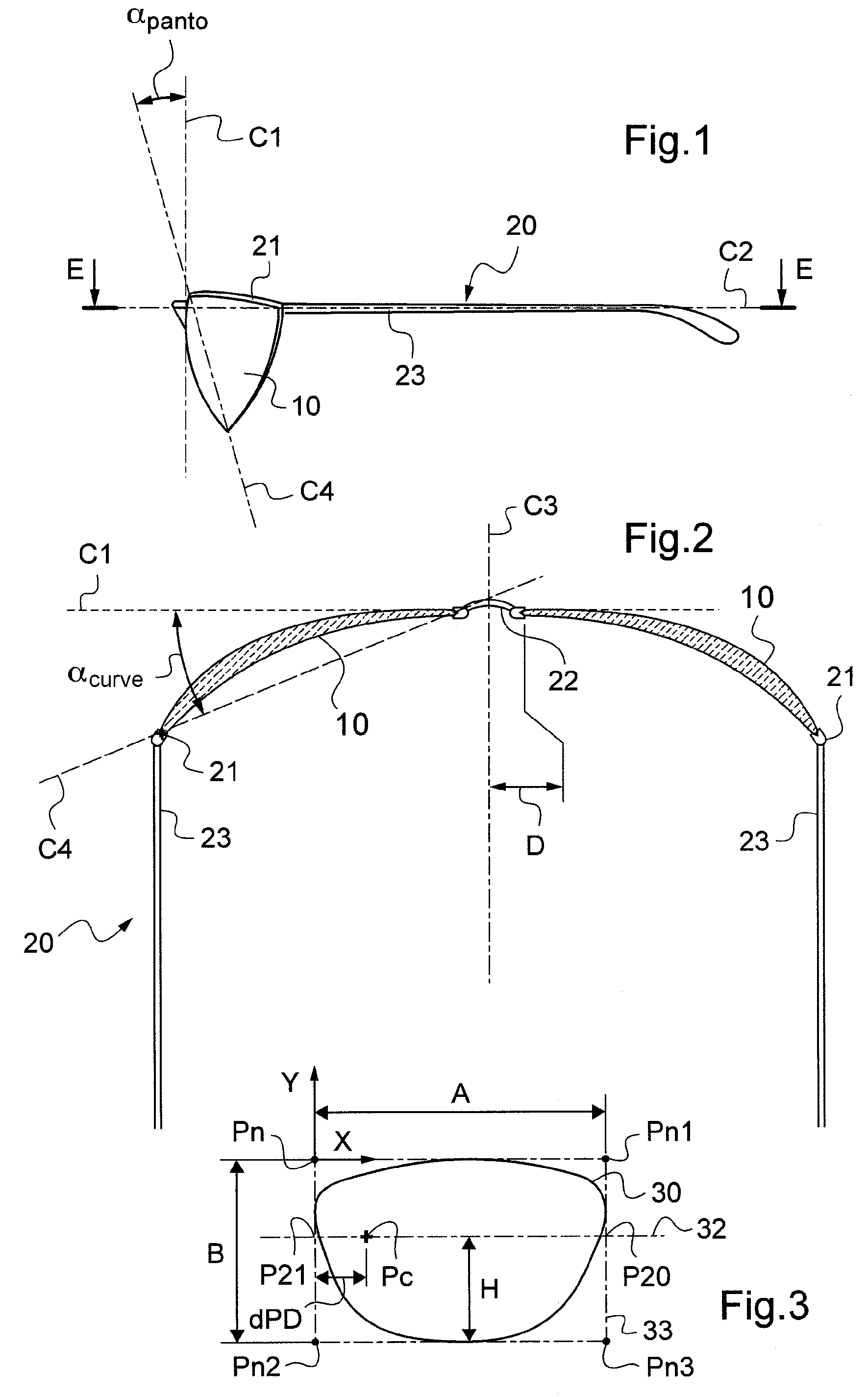
[0043]FIG. 1 is a diagrammatic side view of a pair of rimmed eyeglass;

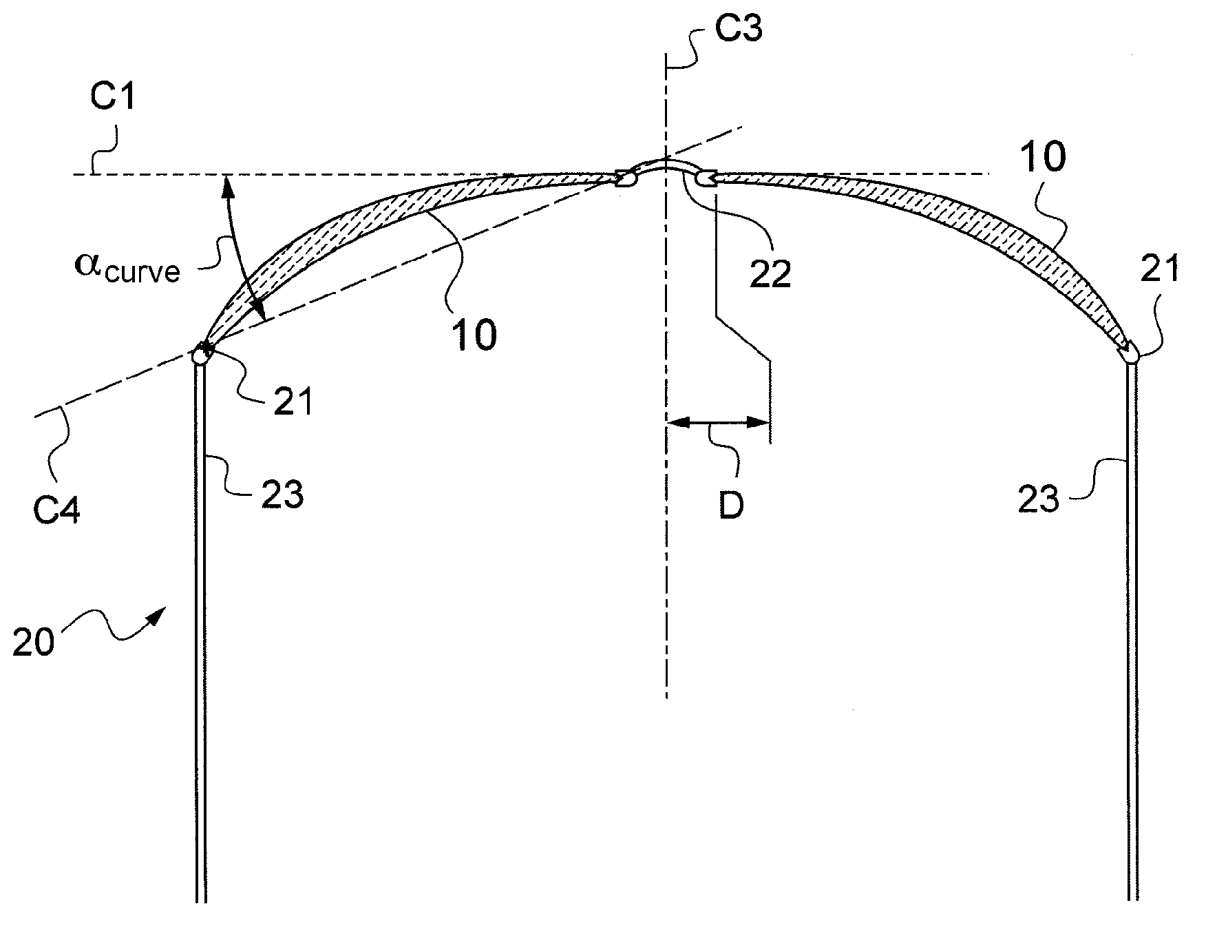
[0044]FIG. 2 is a diagrammatic view of the FIG. 1 pair of eyeglasses in section on plane E-E;

[0045]FIG. 3 is a plane projection of a longitudinal profile representative of the shape of one of the rims of the frame of the FIG. 1 pair of eyeglasses;

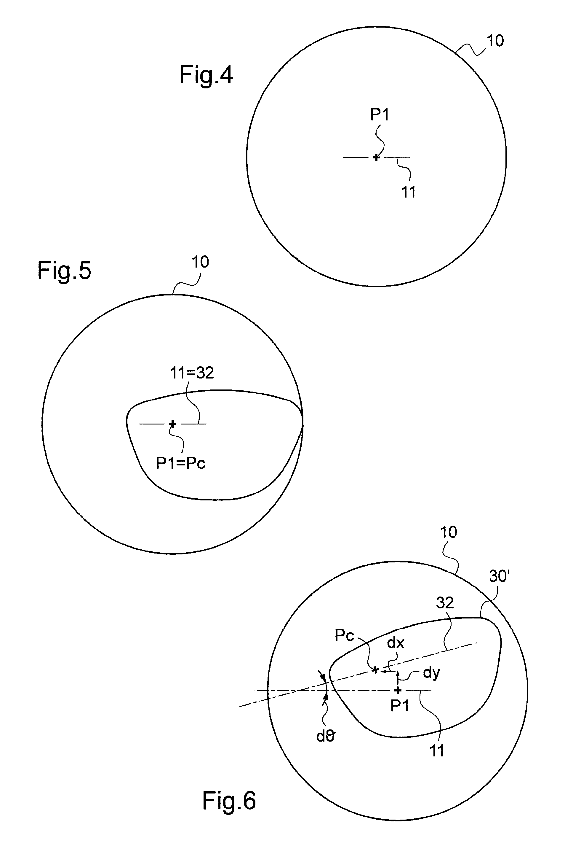
[0046]FIG. 4 is a diagrammatic face view of an ophthalmic lens that has not been shaped;

[0047]FIG. 5 is a diagrammatic face view of the FIG. 4 ophthalmic lens, with the longitudinal profile of FIG. 3 superposed thereon;

[0048]FIG. 6 is a diagrammatic face view of the FIG. 4 ophthalmic lens with the longitudinal profile of FIG. 3 put into coincidence therewith;

[0049]FIG. 7 is a general perspective view of a centering-and-blocking device;

[0050]FIG. 8 is ...


PUM


Abstract

A preparation method includes:acquiring a frame of reference of ophthalmic lens defined at least by a first centering point and by a first orientation direction;acquiring a frame of reference of the rim of the eyeglass frame defined at least by a second centering point and a second orientation direction;acquiring a longitudinal profile representative of the shape of the rim and identified in the frame of reference of the rim;acquiring a curvature parameter or a curvature compensation parameter relating to the camber of the eyeglass frame; andputting the two frames of reference into coincidence, by positioning the two centering points relative to each other and by orienting the two orientation directions relative to each other as a function of the curvature parameter or the curvature compensation parameter so as to define the position and the orientation of the longitudinal profile in the frame of reference of the ophthalmic lens.

Description

TECHNICAL FIELD TO WHICH THE INVENTION RELATES[0001]The present invention relates in general to the field of eyeglasses and more particularly to mounting ophthalmic lenses of a pair of corrective lenses in a frame.[0002]The invention relates more particularly to a method of preparing an ophthalmic lens for mounting in a rim of an eyeglass frame.[0003]A particularly advantageous application of the invention lies in centering ophthalmic lenses for mounting in eyeglass frames that are strongly cambered.TECHNOLOGICAL BACKGROUND[0004]The technical portion of an optician's profession consists in mounting a pair of ophthalmic lenses in a frame selected by a wearer. Such mounting comprises four main operations:[0005]reading the outlines of the bezels in the rims of the frame selected by the wearer, i.e. the outlines of the grooves that run around the inside of each of the rims of the frame, said reading providing an image of the shape of the final outline that is to be presented by each oph...

Claims


Application Information

Patent Timeline
Patent Type & Authority Applications(United States)
IPC IPC(8): G02C13/00
CPCG02C13/005
Inventor BOUTINON, STEPHANE
Owner ESSILOR INT CIE GEN DOPTIQUE
Why Eureka
Try Eureka