Electromechanical Vlave

a technology of electronic components and valves, applied in the field of valves, can solve the problems of long response time, low flow capacity, wear, sticking and leakage, etc., and achieve the effect of accurate control of flow and pressure, short opening and closing tim

Active Publication Date: 2010-07-01
SO ELEKTRONIK
View PDF12 Cites 10 Cited by
  • Summary
  • Abstract
  • Description
  • Claims
  • Application Information

AI Technical Summary

Benefits of technology

[0013]The electronic valve in accordance with the present invention will provide a robust electromagnetic valve that can be controlled with short opening and closing time thereby enabling an accurate control of flow and pressure.

Problems solved by technology

Among disadvantages with today's electromechanical valves are low flow capacity, long response times, wearing, sticking and leakage.

Method used


Image

  • Electromechanical Vlave
  • Electromechanical Vlave
  • Electromechanical Vlave

Examples


Embodiment Construction

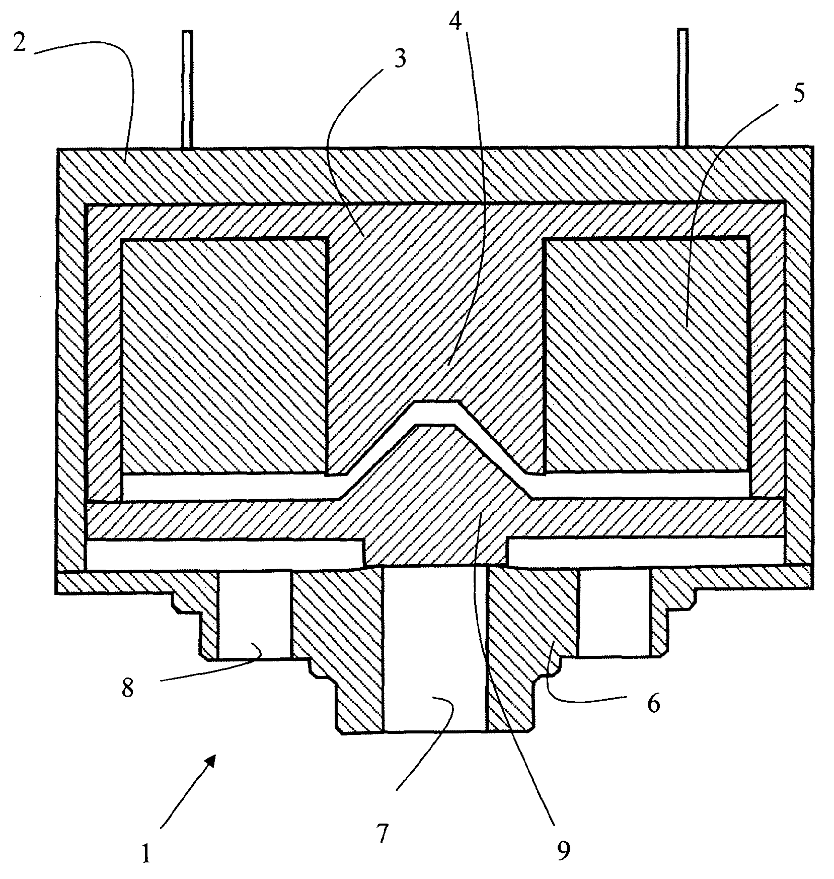
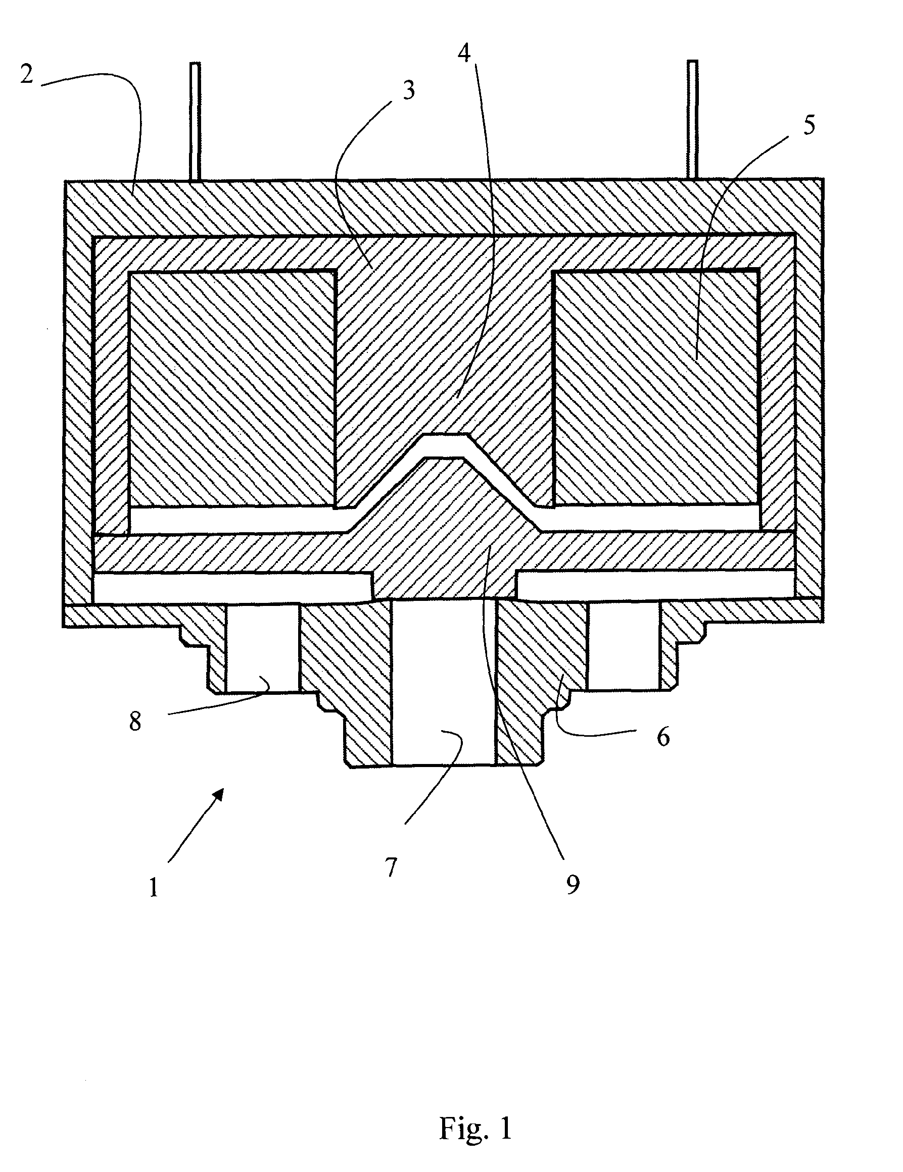
[0018]In FIG. 1, an axial section of an embodiment of an electromechanical valve 1, e.g. a pneumatic valve, according to the invention is shown.

[0019]The valve 1 comprises in a housing 2 of non-magnetic material, e.g. aluminium. Inside the housing 2 a core 3 of an electromagnetic material is located. The core 3 has a centrally extending portion 4 that is surrounded by a coil 5. In one embodiment the core 3 is generally cup-shaped. In one embodiment the core 3 can be E-shaped.

[0020]In one embodiment, the centrally located portion 4 extends to the rim of the cup shaped electromagnetic core 3. It is however to be understood that the portion 4 may be shorter or longer than the height of the wall of the core.

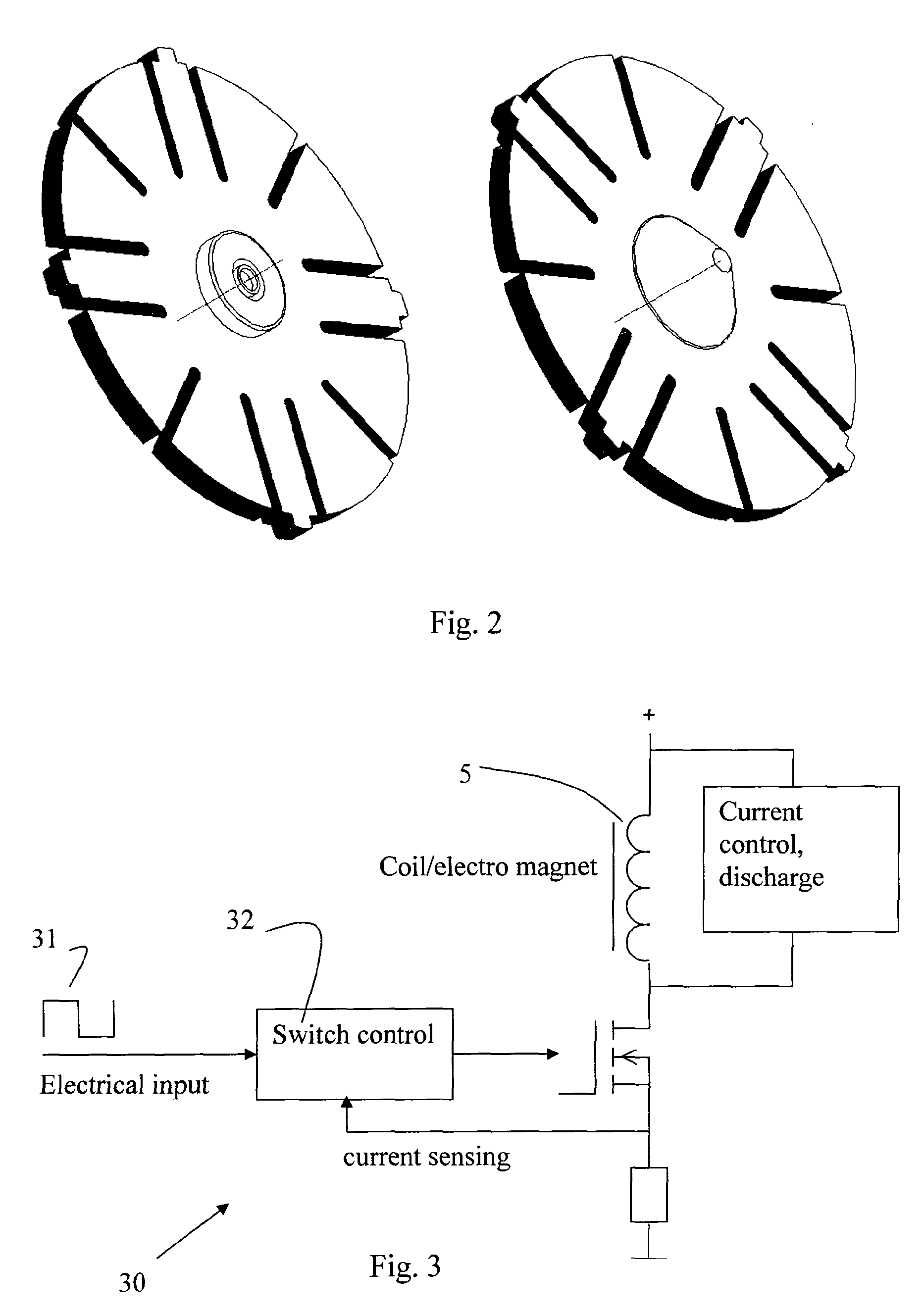
[0021]The coil 5 is supplied with excitation current from a current source such as the one described below in conjunction with FIG. 3 via its terminals.

[0022]Preferably, the coil 5 has low inductance and the current source to be connected to the terminals has current generator charac...


PUM


Abstract

An electromechanical valve (1) comprises in a housing (2), a core (3) of magnetic material surrounded by a coil (5) to be supplied with excitation current, a valve seat (6) attached to the housing (2) with a space to said core (3), at least one centrally located outlet port (7) in said valve seat (6) and at least one inlet port (8) communicating via said space, and a valve washer (9) of magnetic material suspended in said to close said outlet port (7) in absence of excitation current to said coil (5), said valve washer (9) cooperating with said core (3) to open said outlet port (7) when excitation current is supplied to said coil (5).

Description

TECHNICAL FIELD[0001]The invention relates generally to valves and more specifically to an electromechanical valve.BACKGROUND OF THE INVENTION[0002]Among disadvantages with today's electromechanical valves are low flow capacity, long response times, wearing, sticking and leakage. Hence there exists a need for an improved electromagnetic valve.SUMMARY OF THE INVENTION[0003]The object of the invention is to overcome the disadvantages with today's electromechanical valves and to provide an improved electromagnetic valve.[0004]This object and other are attained by the electromechanical valve according to the present invention as set out in the appended claims.[0005]In accordance with one embodiment the electromagnetic valve comprises a housing, a cup-shaped body of magnetic material having a centrally extending core surrounded by a coil to be supplied with excitation current, a valve seat attached to the housing with a space to said core, at least one centrally located outlet port in sa...

Claims


Application Information

Patent Timeline
Patent Type & Authority Applications(United States)
IPC IPC(8): F16K31/02
CPCF16K31/0658F16K31/082F16K31/06F16K31/0655F16K31/0675H01F2007/086H01F2007/1676
Inventor JOHANSSON, PER-OVE
Owner SO ELEKTRONIK
Why Eureka
Try Eureka