
Spherical emergency cut-off valve

A cut-off valve, emergency technology, applied to the cock, valve details, valve device and other directions including the cut-off device, which can solve the problems of difficult and fast opening and closing, waste of resources, large torque of large-diameter ball valves, etc.

Pending Publication Date: 2021-06-08
青州市科隆阀门有限公司
View PDF0 Cites 0 Cited by
  • Summary
  • Abstract
  • Description
  • Claims
  • Application Information

AI Technical Summary

Problems solved by technology

To make the valve have a sealing function, the traditional ball must rely on a strong locking force to make the valve seat and the ball tightly fit to achieve the sealing function. When the traditional ball reaches the sealing state, the opening and closing torque is too large, and most of them are slightly larger. The caliber ball must be equipped with auxiliary devices to operate. At the same time, during the whole process of opening and closing, the sealing part between the ball and the valve seat is severely worn. This defect often causes valve leakage and affects the normal use of the valve.
In order to be able to produce normally, enterprises must frequently replace or repair, resulting in a waste of a lot of resources and a greater potential safety hazard
It is also because of the large torque of large-diameter ball valves that it is difficult to achieve rapid opening and closing. Therefore, there is currently no emergency shut-off valve with large-diameter spherical sealing in the domestic and foreign markets. This has seriously affected the safety of industrial production.

Method used


Image

  • Spherical emergency cut-off valve
  • Spherical emergency cut-off valve
  • Spherical emergency cut-off valve

Examples


Embodiment Construction

[0025] The following will clearly and completely describe the technical solutions in the embodiments of the present invention with reference to the accompanying drawings in the embodiments of the present invention. Obviously, the described embodiments are only some, not all, embodiments of the present invention. Based on the embodiments of the present invention, all other embodiments obtained by persons of ordinary skill in the art without making creative efforts belong to the protection scope of the present invention.

[0026] In the description of this document, it is to be understood that the terms "center", "upper", "lower", "front", "rear", "left", "right", "vertical", "horizontal" , "Top", "Bottom", "Inner", "Outer" and other indicated orientations or positional relationships are based on the orientations or positional relationships shown in the drawings, and are only for the convenience of describing this patent and simplifying the description, rather than indicating or ...


PUM


Abstract

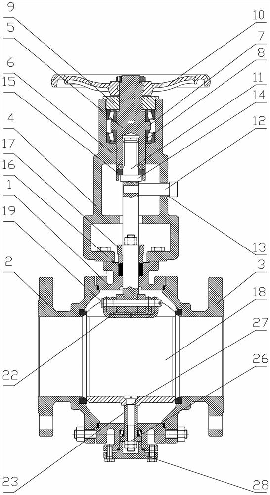
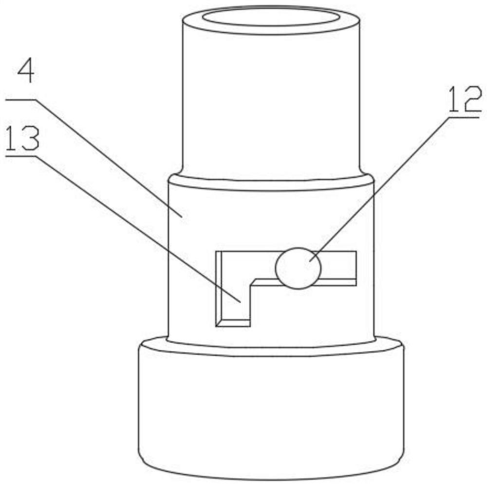
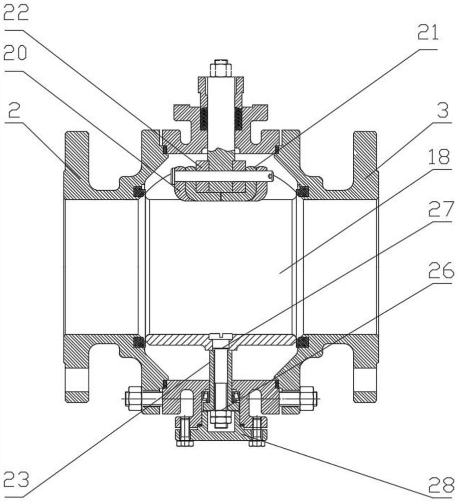
The invention discloses a spherical emergency cut-off valve. A spherical valve element is arranged in an inner cavity of a valve body, a notch is formed in the top of the spherical valve element, and a trapezoidal supporting block with the narrow lower portion and the wide upper portion is arranged in the notch; the inner side of a connecting sleeve is rotationally connected with a driving shaft, the bottom of the driving shaft is in threaded connection with an upper valve rod, a first boss corresponds to the bottom end face of the driving shaft, a limiting rod is fixedly connected to the side wall of the upper valve rod, and the bottom end of the upper valve rod penetrates the valve body to be fixedly connected with the supporting block; and an inverted-L-shaped groove hole is formed in the side wall of the connecting sleeve. When a hand wheel rotates anticlockwise, the driving shaft drives the upper valve rod to ascend, the horizontal section of the inverted-L-shaped groove hole rotates by 90 degrees to reach the other side of the horizontal section of the inverted-L-shaped groove hole, and due to the limiting function of the limiting rod, the driving shaft continues to rotate anticlockwise to drive the upper valve rod to continue to ascend till the bottom end face of the driving shaft and the upper end face of the first boss of the upper valve rod are attached and locked. Otherwise, the rotating driving shaft pushes the upper valve rod to move downwards till the valve is closed.

Description

technical field [0001] The invention relates to the technical field of valves, in particular to a spherical emergency cut-off valve. Background technique [0002] At present, the sealing of the emergency shut-off valve installed and used on the pipeline mainly depends on the tight fit of the sealing surfaces at both ends of the ball in the valve cavity and the left and right sealing parts of the valve body to realize the sealing function. To make the valve have a sealing function, the traditional ball must rely on a strong locking force to make the valve seat and the ball tightly fit to achieve the sealing function. When the traditional ball reaches the sealing state, the opening and closing torque is too large, and most of them are slightly larger. The sphere of the caliber must be equipped with auxiliary devices to operate. At the same time, during the whole process of opening and closing, the sealing part between the sphere and the valve seat is severely worn. This defect...

Claims


Application Information

Patent Timeline
IPC IPC(8): F16K5/06F16K5/08F16K41/02
CPCF16K5/06F16K5/0647F16K5/0663F16K41/026
Inventor 洪俊瑜洪墨飞
Owner 青州市科隆阀门有限公司
Learn More